3-Series Control System™ Crestron MC3
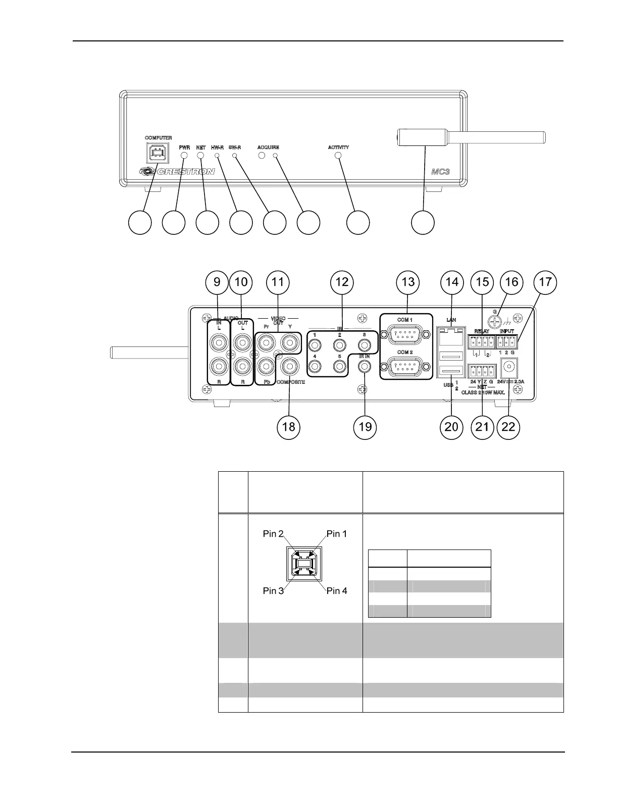
MC3 (Front View)
2 3 4 5 6 71 8
MC3 (Rear View)
Connectors, Controls & Indicators
#
CONNECTORS
1
,
CONTROLS &
INDICATORS
DESCRIPTION
1
COMPUTER
(1) USB Type B female
USB 2.0 computer console port
6 ft (2 m) cable included
PIN DESCRIPTION
1 +5 VDC
2 Data -
3 Data +
4 Ground
2 PWR LED
(1) Green LED, indicates operating power
supplied from power pack or Cresnet
network
3 NET LED
(1) Amber LED, indicates communication
with the Cresnet system
4 HW-R Button (1) Recessed push button for hardware reset
5 SW-R Button (1) Recessed push button for software reset
(Continued on following page)
10 • 3-Series Control System™: MC3 Operations Guide – DOC. 7095D