Crestron MC3 3-Series Control System™
Connectors, Controls & Indicators (Continued)
#
CONNECTORS
1
,
CONTROLS &
INDICATORS
DESCRIPTION
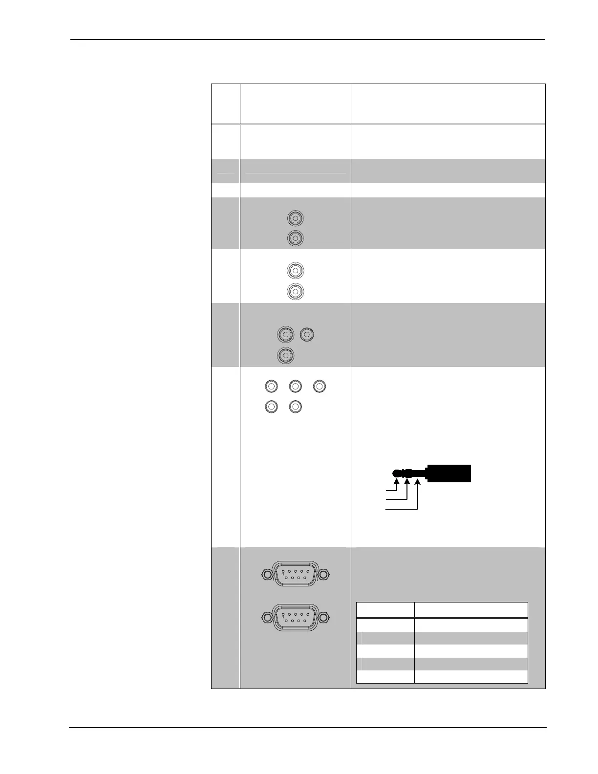
6
ACQUIRE
Button and LED
(1) Recessed push button with red LED,
used to set up connections with wireless
devices
7 ACTIVITY
(1) Red LED, indicates wireless
communications
8 Antenna (1) Connection for supplied antenna
9
AUDIO IN (L – R)
(2) RCA female, unbalanced stereo line-level
audio input;
Input Level: 2 V
rms
maximum;
Input Impedance: 7k Ω nominal
10
AUDIO OUT (L – R)
(2) RCA female, unbalanced stereo line-level
audio output with volume and mute control;
Maximum Output Level: 2 V
rms
;
Output Impedance: 100 Ω nominal
11
VIDEO OUT
(Y, PB, PR)
(3) RCA female, component (YP
b
P
r
) video
output (for future use);
Output Level: 1 V
p-p
nominal (Y), 0.7 V
p-p
nominal (P
b
P
r
);
Output Impedance: 75 Ω nominal
12
IR (1 – 5)
(5) 3.5 mm mini-phone jacks, IR/Serial output
ports;
IR output up to 1.2 MHz;
1-way serial TTL/RS-232 (0-5 Volts) up to
115.2k baud
Use Crestron Infrared Emitter Probe (model
STIRP, sold separately) for controlling
infrared devices. For information on other
serial control cables, contact Crestron.
Tip
Ring
Sleeve
Tip: IR Data Out
Ring: No Connection
Sleeve: Ground
13
COM (1 – 2)
(2) DB9 male, bidirectional RS-232 ports;
Up to 115.2k baud; hardware and software
handshaking support Use with a standard
DB9 straight through cable. Pins 1, 4, 6 and
9 are not used but may be connected.
PIN DESCRIPTION
2 RXD - Receive Data
3 TXD - Transmit Data
5 SG - Signal Ground
7 RTS - Request To Send
8 CTS - Clear To Send
(Continued on following page)
Operations Guide – DOC. 7095D 3-Series Control System™: MC3 • 11