3-Series Control System™ Crestron MC3
Connectors, Controls & Indicators (Continued)
#
CONNECTORS
1
,
CONTROLS &
INDICATORS
DESCRIPTION
14
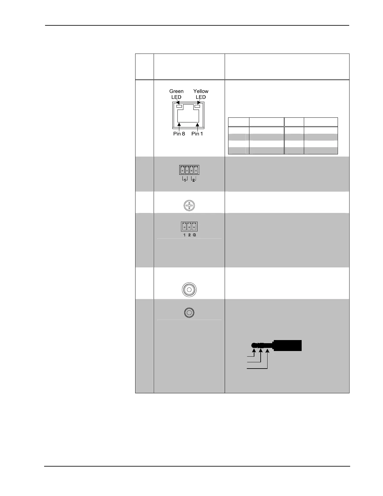
LAN
2
(1) 8-wire RJ-45 jack (8P8C modular
female);
10BASE-T/100BASE-TX Ethernet port
Green LED indicates link status
Yellow LED indicates Ethernet activity
PIN SIGNAL PIN SIGNAL
1 TX + 5 N/C
2 TX - 6 RX -
3 RX + 7 N/C
4 N/C 8 N/C
15
RELAY (1 – 2)
(1) 4-pin 3.5 mm detachable terminal block
comprising (2) normally open, isolated
relays;
Rated 1 Amp, 30 Volts AC/DC;
MOV arc suppression across contacts
16
G
(1) 6-32 screw, chassis ground lug
17
INPUT (1 – 2)
(1) 3-pin 3.5 mm detachable terminal block
comprising (2) programmable digital inputs
(referenced to GND);
Input Voltage Range: 0-24 Volts DC;
Logic Threshold: ≥1.2 Volts DC active/high,
≤0.46 Volt DC inactive/low;
Input Impedance: 2.2k Ohms pulled up to
5 Volts
18
VIDEO OUT
(COMPOSITE)
(1) RCA female, composite video output (for
future use);
Output Level: 1 V
p-p
nominal;
Output Impedance: 75 Ω nominal
19
IR IN
(1) 3.5 mm TRS mini-phone jack;
For connection of the CNXRMIRD IR
receiver
3
;
Allows IR wireless control from Crestron and
third-party remotes using RC-5 IR
commands.
Tip
Ring
Sleeve
Tip: IR Data In
Ring: +5 VDC
Sleeve: Ground
(Continued on following page)
12 • 3-Series Control System™: MC3 Operations Guide – DOC. 7095D