Crestron MC3 3-Series Control System™
Connectors, Controls & Indicators (Continued)
#
CONNECTORS
1
,
CONTROLS &
INDICATORS
DESCRIPTION
20
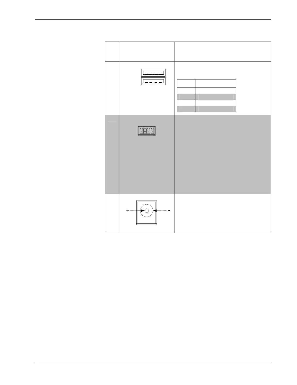
USB (1 – 2)
Pins 1 2 3 4
(2) USB Type A female;
USB 2.0 ports for storage and
mouse/keyboard devices
PIN DESCRIPTION
1 +5 VDC
2 Data -
3 Data +
4 Ground
21
NET
4
(24 Y Z G)
(1) 4-pin 3.5 mm detachable terminal block,
Cresnet master port;
Sources power to Cresnet devices with
power pack connected to 24VDC power input
jack;
May be used as alternate power input to
receive operating power from the Cresnet
network in lieu of a local power pack;
Refer to “Power Requirements” in the “MC3
Specifications” table for additional
specifications.
24: Power (24 Volts DC)
Y: Data
Z: Data
G: Ground
22
24VDC 2A
4
(1) 2.1 mm barrel DC power jack;
24 Volt DC power input power pack included;
Passes through to NET port to power
Cresnet devices;
Refer to “Power Requirements” in the “MC3
Specifications” table for additional
specifications.
1. Interface connectors for RELAY, INPUT and NET ports are provided with the unit.
2.
To determine which is pin 1 on the cable, hold the cable so the end of the eight pin modular plug is
facing away from you, with the clip down and copper side up. Pin 1 is on the far left.
3. Sold separately.
4.
The MC3 can be powered via the 24 VDC jack or the NET port. Be sure to use a Crestron approved
power supply as another may cause damage.
Operations Guide – DOC. 7095D 3-Series Control System™: MC3 • 13