Crestron MC3 3-Series Control System™
Input/Output Control
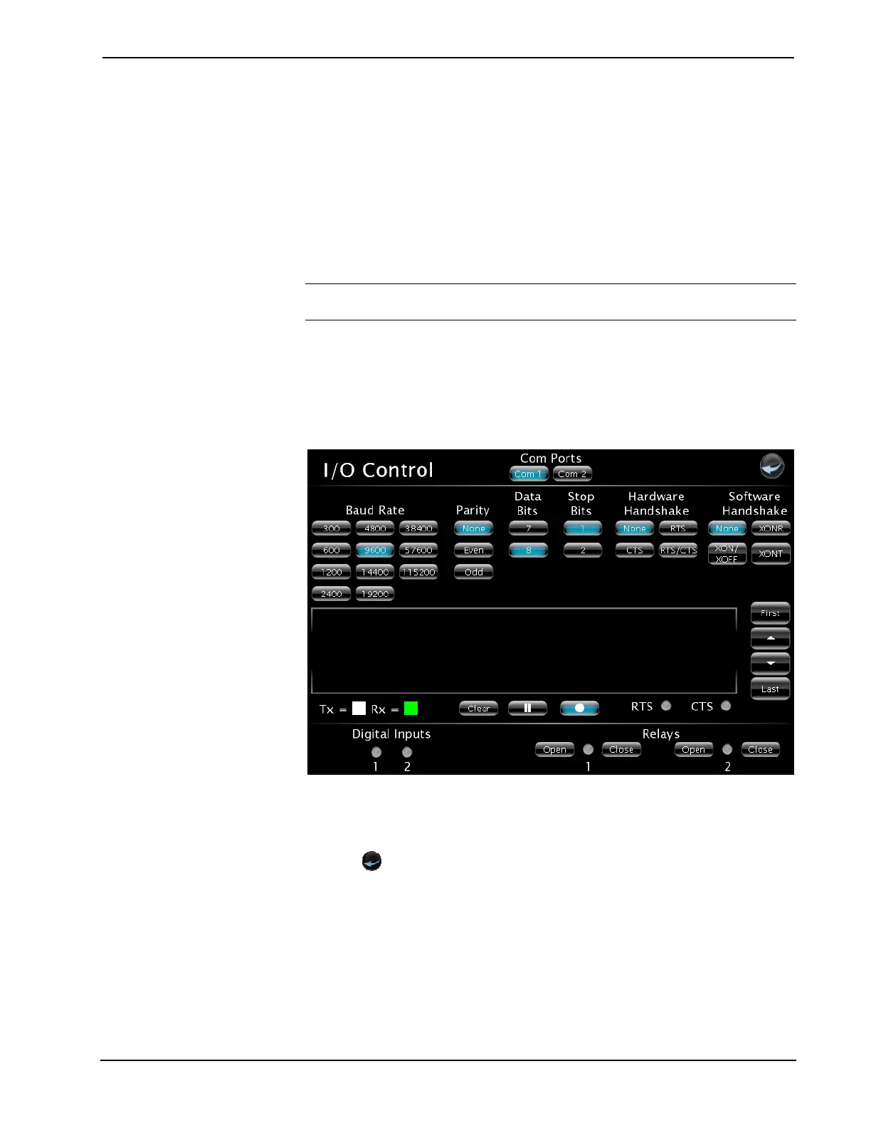
Click Input/Output Control from the “MC3 Setup” screen to open the “I/O
Control” screen. The MC3 allows control over a wide array of devices which may
require specific communication settings. Use this screen to configure the control
settings.
Select Com 1 or Com 2 and make the appropriate selections for the device
connected to the MC3. The screen will display communication messages that are
made between the device and the MC3. Use the record button to store the last 20
lines of data.
NOTE: Twenty lines of data are stored on the MC3, only five are displayed on the
screen.
Press the pause button to interrupt the recording but allow the data log to remain
intact. The Clear button clears the data stored in the screen. Refer to the following
image for visual guidance.
The status of the digital inputs is indicated by the green on screen LEDs.
“I/O Control” Screen
The Open and Close buttons for the relays allow testing of the connected devices.
Click the Open/Close button to test the device. The on screen LED illuminates green
to show that the relay is closed.
Press the
icon to return to the previous page.
Diagnostics
From the “MC3 Setup” screen click on Diagnostics to enter the “Diagnostics”
screen. The “Diagnostics” screen contains buttons that provide information about the
connected devices, hardware configuration and error logs.
Click on the Show Cresnet Devices or Show InfiNET EX Devices to display the
Cresnet or infiNET devices that are connected to the network. Refer to the following
image for visual guidance.
Operations Guide – DOC. 7095D 3-Series Control System™: MC3 • 31