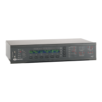
Crestron AV2 & PRO2 2-Series Integrated Dual Bus Control System
Industry Compliance
As of the date of manufacture, this unit has been tested and found to comply with
specifications for CE marking and standards per EMC and Radiocommunications
Compliance Labelling (N11785).
NOTE: This device complies with part 15 of the FCC rules. Operation is subject to
the following two conditions: (1) this device may not cause harmful interference, and
(2) this device must accept any interference received, including interference that may
cause undesired operation.
Setup
Rack Mounting
WARNING: To prevent bodily injury when mounting or servicing this unit in a
rack, take special precautions to ensure that the system remains stable. The following
guidelines are provided to ensure your safety:
The unit should be mounted at the bottom of the rack if it is the only unit in the
rack.
When mounting this unit in a partially filled rack, load the rack from the bottom
to the top with the heaviest component at the bottom of the rack.
If the rack is provided with stabilizing devices, install the stabilizers before
mounting or servicing the unit in the rack.
NOTE: If rack mounting is not required, rubber feet are provided for shelf placement
or stacking. Apply the feet near the corner edges on the underside of the unit.
NOTE: Reliable earthing of rack-mounted equipment should be maintained.
Particular attention should be given to supply connections other than direct
connections to the branch circuit. (e.g., use of power strips).
Two “ears” are provided with the 2-Series integrated dual bus control system so that
the unit can be rack mounted. These ears must be installed prior to mounting.
Complete the procedure below to attach ears to the unit. The only tool required is a
#2 Phillips screwdriver.
1. There are 12 screws (#6-32 x 0.375" LG) that secure the sides of the
2-Series control system top cover. Using a #2 Phillips screwdriver,
remove the three screws closest to the front panel from one side of the
unit.
Operations Guide - DOC. 5957A Integrated Dual Bus Control System: AV2 & PRO2 • 15