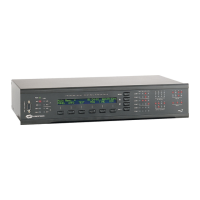
Crestron AV2 & PRO2 2-Series Integrated Dual Bus Control System
Network Wiring
NOTE: When making wire connections, refer to the latest revision of the Cresnet
Network Interconnect Drawing (Doc. 5411). The document can be obtained from the
Downloads | Product Manuals section of the Crestron website (www. crestron.com).
CAUTION: Possible equipment damage if miswired.
CAUTION: Exceeding the power output (maximum 50W) of the 2-Series
integrated dual bus control system can result in system shutdown or a blown fuse.
NOTE: Do not power up system until all wiring is verified. Care should be taken to
ensure data (Y, Z) and power (24, G) connections are not crossed.
NOTE: For larger networks (i.e., greater than 28 network devices), it may be
necessary to add a Cresnet Hub/Repeater (CNXHUB) to maintain signal quality
throughout the network. Also, for networks with lengthy cable runs, it may be
desirable to add a hub/repeater after only 20 network devices.
NOTE: Each 2-Series integrated dual bus control system has one 4-pin network
connector. Use the following Crestron products to interconnect to other devices
within a network (some permit network testing):
- CNTBLOCK, Network Terminal Block
- CNHBLOCK, Multi-Type Network Distribution Block
- CNXHUB, Cresnet Hub/Repeater
- ST-CNB, SmarTouch/Cresnet Terminal Expander
When calculating the wire gauge for a particular network run, the length of the run
and the power factor of each network unit to be connected must be taken into
consideration. If network units are to be daisy-chained on the run, the power factor
of each network unit to be daisy-chained must be added together to determine the
power factor of the entire chain. The length of the run in feet and the power factor of
the run should be used in the following resistance equation to calculate the value on
the right side of the equation.
Resistance Equation
R = Resistance (refer to table below).
L = Length of run (or chain) in feet.
PF = Power factor of entire run (or chain).
R <
L x PF
40,000
Where:
The required wire gauge should be chosen such that the resistance value is less than
the value calculated in the resistance equation. Refer to the table after this paragraph.
Operations Guide - DOC. 5957A Integrated Dual Bus Control System: AV2 & PRO2 • 17