2-Series Integrated Dual Bus Control System Crestron AV2 & PRO2
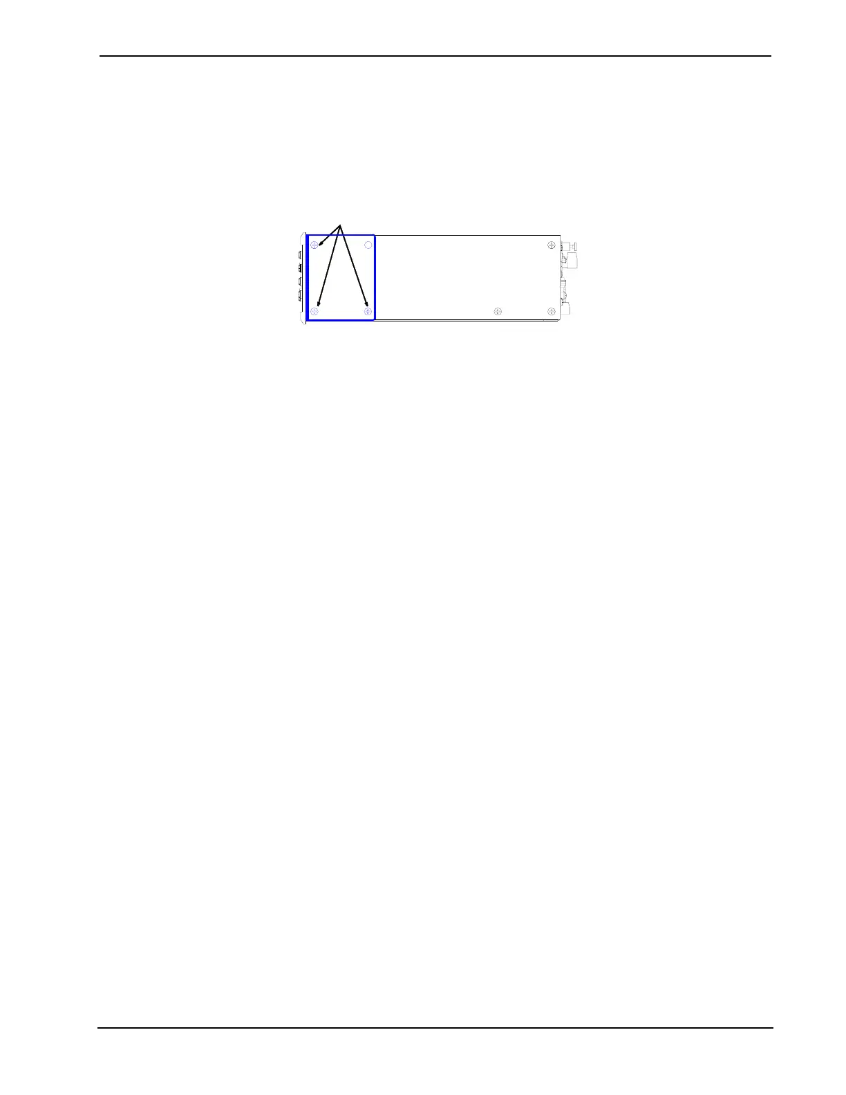
2. Position a rack ear so that its mounting holes align with the holes
vacated by the screws in step 1.
3. Secure the ear to the unit with three screws from step 1, as shown in the
illustration after this step.
Ear Attachment for Rack Mounting (PRO2 shown in illustration)
FASTEN WITH THE SAME (3) COVER SCREWS
RIGHT SIDE VIEW OF PRO2 WITH
OPTIONAL RACK MOUNTING EARS INSTALLED
4. Repeat procedure (steps 1 through 3) to attach remaining ear to
opposite side.
Bussing Strip Installation
The 2-Series integrated dual bus control system is supplied with two brass bussing
strips to facilitate commoning (linking) of multiple terminal block connections. The
bussing strips are constructed with four terminal block position, and may be trimmed
to size for various applications or different devices. One strip is supplied for each
8-position terminal block.
1. To utilize the bussing strip, determine the number of relays to be
commoned for the equipment being installed. If less than four, the strip
can be trimmed to size with a pair of scissors or wire snips.
2. Loosen the terminal block screws and insert the first leg of the bussing
strip into the first common position on the terminal block. The strip
engages the other common positions automatically.
3. Remove approximately 1/8" of the jacket from the common wire and
insert the conductor into one of the terminal block common positions.
Tighten the terminal block screws to lock the wire and bussing strip
into place. Insulate the strip by folding a piece of ¾" wide vinyl
electrical tape (such as Scotch 33+) over the spine and as much of the
individual legs as possible. Excess tape at each end of the strip should
be pressed closed, then trimmed to within approximately 1/16" of the
end of the strip.
4. When wiring the remaining conductors, remove approximately 1/8" of
the jacket and insert the wires into the proper terminal block positions.
To prevent the possibility of electrical shorts, it is essential that these
conductors do not touch any uninsulated portion of the bussing strip.
5. Securing a tie wrap around the bussing strip is a useful way to strain
relieve the wires connected to the terminal block.
16 • Integrated Dual Bus Control System: AV2 & PRO2 Operations Guide - DOC. 5957A