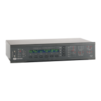
Crestron AV2 & PRO2 2-Series Integrated Dual Bus Control System
2-Series Integrated Dual Bus Control System Troubleshooting
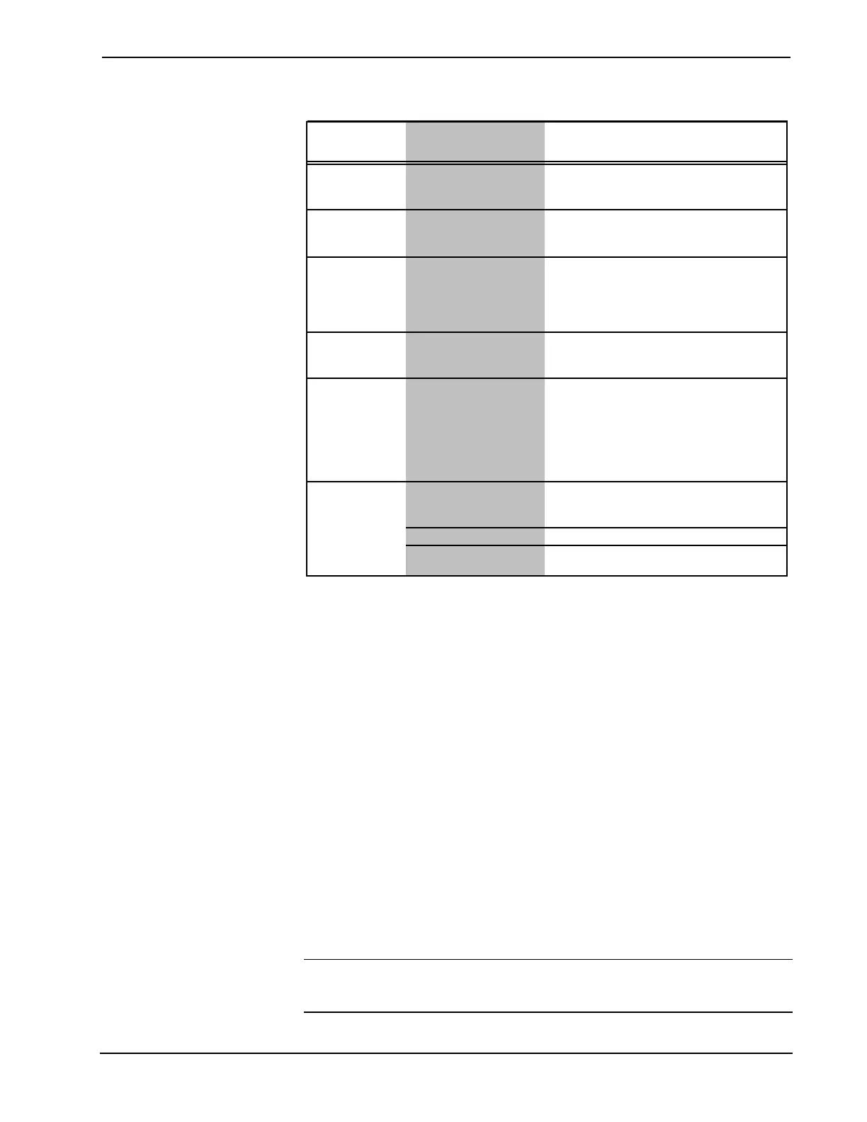
TROUBLE
POSSIBLE
CAUSE(S)
CORRECTIVE ACTION
Unexpected
response from
control system.
Network devices are not
communicating to the
control system.
From the Viewport, poll the network (F4) to
verify communication.
PWR LED does
not illuminate.
Control system is not
receiving power.
Verify that supplied power cord is properly
attached to control system and the other end is
securely plugged into an outlet.
ERR LED
illuminates.
Hardware or software
failure, hardware
incompatibility with
software definitions, or
programming error.
Verify that hardware configuration matches
software configuration (i.e., card is in proper
slot as defined by program). If using PRO2,
depress MSG button on front panel for specific
error. Use Viewport to display the error log.
Compilation error
RLCMCVT166 &
RLCMCVT177.
Poor analog versus serial
signal definition in the
SIMPL Windows program.
Confirm proper signal definition in the program.
System locks up. Various.
Hold down
SW-R
button on control system
front panel to bypass program and
communicate directly with processor. Refer to
"Troubleshooting Communications" for more
details. Refer also to the "Troubleshooting Non-
Functioning Units" procedures following this
table.
A/V system device
does not respond.
IRP2 or serial port not
placed properly.
Verify placement of IRP2 (hold phosphor card
under IRP2 while pressing button) and tighten
serial cables.
Used wrong IR/serial port. Verify that proper IR or serial port is defined.
Serial cable miswired. Verify that serial cable is wired correctly for RS-
232, 422, 485.
Troubleshooting Non-Functioning Units
Perform the following procedures to correct system lock-up problems that are not
resolved via the procedures in “Troubleshooting Communications” on page 21.
1. Connect a DB9 straight-through RS232 cable between the AV/PRO2 and a
PC. Refer to “Establishing Communication with the AV2/PRO2” on page
19 for more information.
2. Open Viewport and select Setup | Communication Settings to open the
“Port Settings” window.
3. In the window, select RS-232 (Connection Type), 57600 (Baud Rate), N
(Parity), 8 (Data Bits) and 1 (Stop Bits) and click OK.
4. Power down the AV2/PRO2.
5. While powering up the AV2/PRO2, press and hold ALT and K on the
keyboard until the following text (or similar) appears in Viewport:
System Monitor [v1.001 (0001)]
12-19-01 16:25:23 32 MB RAM, 4MB FLASH
CS>
NOTE: After this, you can increase the baud rate to 115200 (for faster
communication) by pressing F8 on the keyboard and then selecting 115200 from the
“Set Baud Rate” window.
Operations Guide - DOC. 5957A Integrated Dual Bus Control System: AV2 & PRO2 • 39