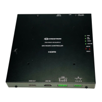
DigitalMedia™ Room Controller, CAT Crestron DM-RMC-100
Connectors, Controls & Indicators (Continued)
# CONNECTORS
1
,
CONTROLS &
INDICATORS
DESCRIPTION
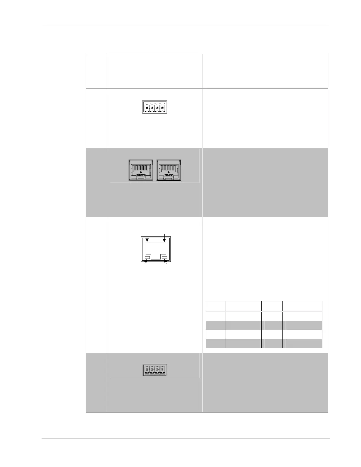
16 IR (1-2)
(1) 4-pin 3.5 mm detachable
terminal block comprising
two IR/Serial ports;
IR output up to 1.1 MHz;
1-way serial TTL/RS-232
(0-5 Volts) up to 19200 baud
3
12 DM INPUT
4, 5
(1) DM CAT input composed of
two 8-pin RJ-45 female,
shielded;
Connects to DM CAT output of
a DM switcher, transmitter, or
other DM device via DM-CBL
cable
6
13 LAN
4
Green
LED
Yellow
LED
Pin 8
Pin 1
(1) 8-wire RJ-45 with two LED
indicators;
10BASE-T/100BASE-TX
Ethernet port;
Green LED indicates link
status;
Yellow LED indicates Ethernet
activity
PIN SIGNAL PIN SIGNAL
1 TX + 5 N/C
2 TX - 6 RX -
3 RX + 7 N/C
4 N/C 8 N/C
14 24 A B G
7, 8
(1) 4-pin 3.5 mm detachable
terminal block, DMNet port;
Connects to DMNet port of a
DM switcher, transmitter, or
other DM device via DM-CBL
cable
6
16 • Room Controller, CAT: DM-RMC-100 Operations & Installation Guide – DOC. 6743-1F
 Loading...