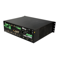
DigitalMedia Presentation Systems Crestron DMPS-100/200/300-C/300-C-AEC
22 • DigitalMedia Presentation Systems: DMPS-100/200/300-C/300-C-AEC Operations Guide – DOC. 7219D
NOTE: In the following table, the reference designation and quantity of several of
the connectors and indicators vary between the DMPS-100/200/300-C models. Refer
to the previous illustrations and the description in the table for clarification.
Connectors, Controls & Indicators
# CONNECTORS
,
CONTROLS &
INDICATORS
DESCRIPTION
1 NET LED (1) Yellow LED, indicates Cresnet bus activity
2 LAN LED (1) Yellow LED, indicates Ethernet activity
3 HW-R (1) Recessed miniature push button for hardware
reset, reboots the control system
4 SW-R (1) Recessed miniature push button for software
reset, restarts the SIMPL program
5 POWER (1) Push button and green LED, programmable
for system power control
6 Softkeys (4) Push buttons for activation of LCD driven
functions and passcode entry
7 LCD Green LCD alphanumeric, adjustable backlight;
2 lines x 20 characters per line;
Displays input/outputs by name, volume levels,
setup menus, signal routing, device info, and
other system information
8 MENU (1) Push button, provides access to the entire
menu structure, and during configuration
process, steps menu back one level
9
Λ, V
(2) Push buttons, scroll up or down through
menu and adjust menu parameters
10 ENTER (1) Push button, executes highlighted menu or
value
11 VOLUME
(1) Continuous turn rotary encoder, adjusts menu
parameters, defaults to program audio volume
12 MUTE (1) Push button and red LED, mutes the program
audio output
13 ROUTE
(1) Push button and red LED, selects Route
mode to allow routing changes
14 VIEW
(1) Push button and red LED, selects View mode
to view current routing
15 INFO
(1) Push button and red LED, selects Info mode
to view AV and device info
16 INPUTS (4) Push buttons and red LEDs, select input to be
routed, for DMPS-100-C
(6) Push buttons and red LEDs, select input to be
routed, for DMPS-200-C
(7) Push buttons and red LEDs, select input to be
routed, for DMPS-300-C
(Continued on following page)

 Loading...