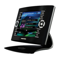
15 Inch Tilt Touchpanel Crestron Isys™ TPS-6000
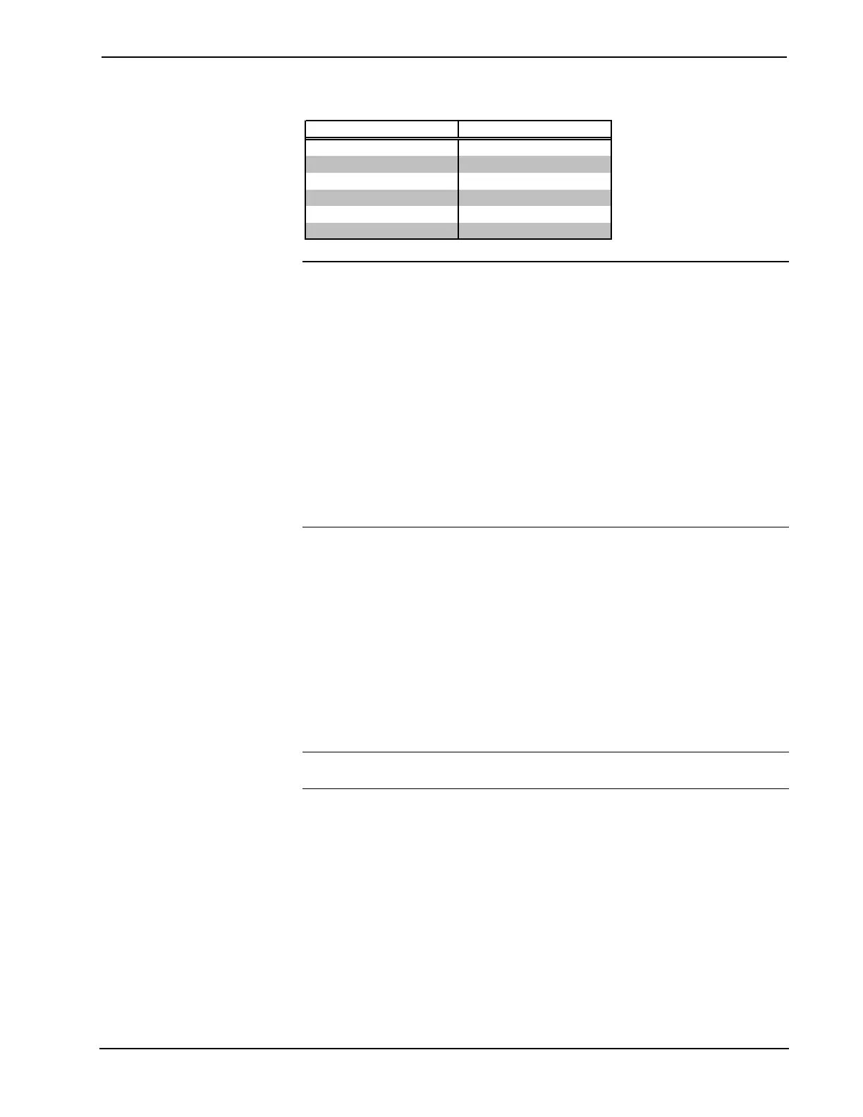
Wire Gauge Values
RESISTANCE (R) WIRE GAUGE
4
16
6
18
10
20
15
22
13
Doubled CAT5
8.7
Tripled CAT5
NOTE: All network wiring must consist of two twisted pairs. One twisted pair is
the +24V conductor and the GND conductor. The other twisted pair is the Y and Z
conductors.
NOTE: When daisy-chaining Cresnet units, strip the ends of the wires carefully to
avoid nicking the conductors. Twist together the ends of the wires that share a pin on
the network connector, and tin the twisted connection. Apply solder only to the ends
of the twisted wires. Avoid tinning too far up the wires or the end becomes brittle.
Insert the tinned connection into the Cresnet connector and tighten the retaining
screw. Repeat the procedure for the other three conductors.
NOTE: For larger networks (i.e., greater than 28 network devices), it may become
necessary to add a Cresnet Hub/Repeater (CNXHUB) to maintain signal quality
throughout the network. Also, for networks with lengthy cable runs, it may be
necessary to add a Hub/Repeater after only 20 devices.
Identity Code
All equipment and user interfaces within the network require a unique identity code
(Net ID). These codes are two-digit hexadecimal numbers ranging from 03 to FE.
Refer to “Interface Menu” on page 12 for instructions on setting the unit's Net ID.
The Net ID of each unit must match an ID code specified in the SIMPL Windows
program. Refer to “Setting the Net ID in Device Settings” on page 25 for details of
the SIMPL Windows procedure.
Configuring the Touchpanel
NOTE: The only connection required to configure the touchpanel is power (+24V
and Ground). Refer to “Hardware Hookup” on page 19 for details.
10 • 15 Inch Tilt Touchpanel: Crestron Isys™ TPS-6000 Operations Guide - DOC. 5864A
 Loading...