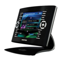
Crestron Isys™ TPS-6000 15 Inch Tilt Touchpanel
Diagnostics Menu
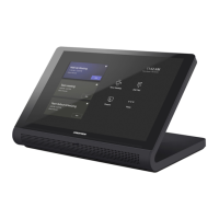
DIAGNOSTICS MENU
The Diagnostics button from the MAIN MENU contains controls for enabling an
Ethernet card (if installed) and diagnostic tools. The diagnostic tools should only be
used under supervision from a Crestron customer service representative during
telephone support. The options available from the DIAGNOSTICS MENU, shown
to the left, are numeric in nature and their interpretation is beyond the scope of this
manual.
NOTE: If the Disable Ethernet button is selected, the touchpanel will not
communicate via TCP/IP or Cresnet Internet Protocol (CIP). Select “Enable
Ethernet” to enable the Ethernet card.
NOTE: The “About…” button will display a screen indicating the current version
of firmware residing on the touchpanel.
Hardware Hookup
Make the necessary connections as called out in the following illustrations. Refer to
“Network Wiring” on page 9 before attaching the NET or NET/VIDEO connector.
Apply power after all connections have been made.
CAUTION: Do not apply excessive pressure to the touchscreen display during
handling. Doing so can crack the screen and damage the touchpanel.
NOTE: Not all ports are active; some require the additional purchase and
installation of an expansion card to enable operation.
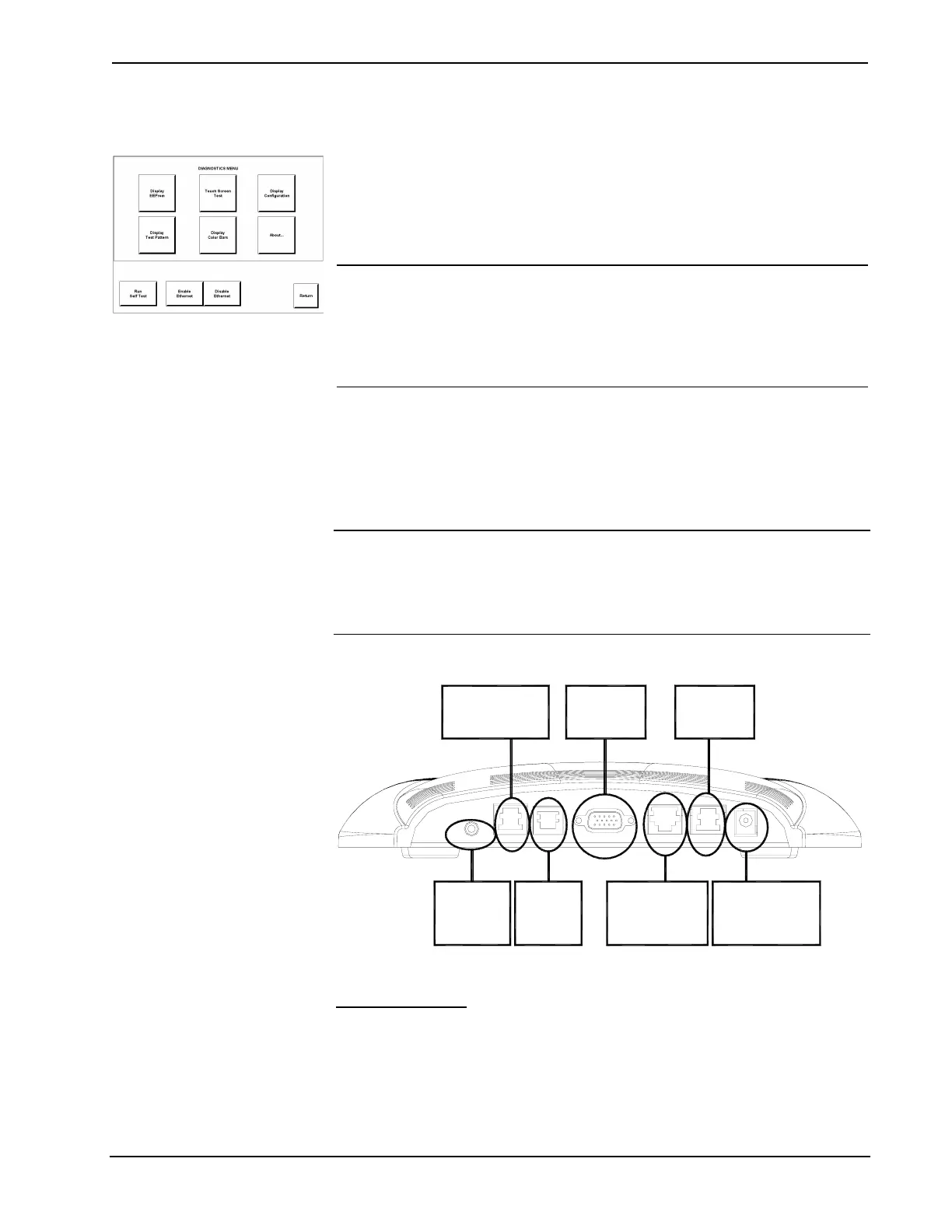
Hardware Connections for the TPS-6000
HEADPHONES:
TO EXTERNAL
HEADPHONE
SET
POWER:
TO POWER PACK
(24VDC, 2A OUTPUT)
NET/VIDEO:
TO CRESNET VIA
TPS-IMPC / INPUTS
COMPOSITE OR
S-VIDEO
RS-232:
TO PC OR
ANY RS-232
DEVICE
HEADPHONES AUDIO RGB LANRS-232 NET/VIDEO 24VDC 2.0A
RGB:
RGB VIDEO
INPUT
ETHERNET:
10/100 BASE-T
ETHERNET TO
LAN OR WEB
AUDIO:
STEREO AUDIO INPUT
& MIC OUTPUT FROM
TPS-IMPC
HEADPHONES
Connect this standard mini phone jack (12mW, 32 ohms load) to the plug of an
external headphone set, not supplied.
Operations Guide - DOC. 5864A 15 Inch Tilt Touchpanel: Crestron Isys™ TPS-6000 • 19
 Loading...