15 Inch Tilt Touchpanel Crestron Isys™ TPS-6000
AUDIO
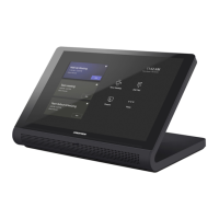
This 8-pin, RJ-45 connector mates with an interface module and provides
differential/single ended audio input and output. It also produces line level
differential output. Description of the pinouts is shown in the following table.
AUDIO Pinouts
TYPE PIN DESIGNATION DESCRIPTION
1 L+ Left Input (Positive)
2 L- Left Input (Negative)
3 GND/Shield Audio Input Ground/Shield
4 R+ Right Input (Positive)
5 R- Right Input (Negative)
6 GND/Shield Mic Output Ground/Shield
7 M+ Mic Output (Positive)
1
8
1
8
Front
Top
8 M- Mic Output (Negative)
To determine the location of pin 1, hold the cable so that the end of the
8-pin RJ45 connector is facing away from you, with the clip side down and the
copper side up. The copper connector on the far left is pin 1.
NOTE: When connecting the touchpanel to the interface module, do not confuse the
8-pin audio cable with the 10-pin net/video cable.
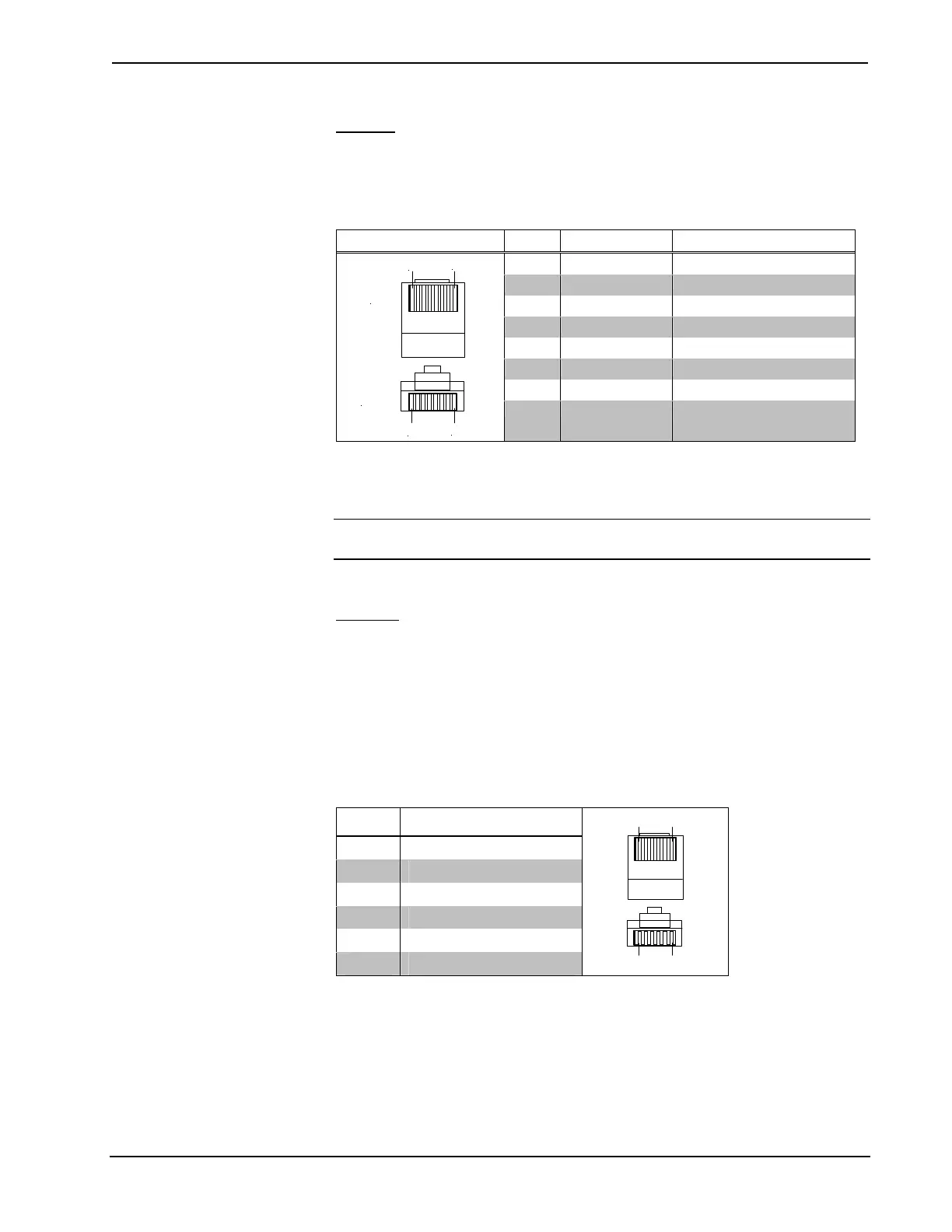
RS-232
This 6-pin RJ-11 connector mates with a serial port of a PC. The connecting cable is
not supplied. Prior to installation, use this port for direct connection between the
touchpanel and a PC to load files to a touchpanel without a network connection. In
the event that modular cables or an RJ-11 to DB9F adapter is not available, the
following table and diagram provide information so that the cable can be fabricated
on site. Refer to “RS-232 Menu” on page 14 for proper RS-232 port configuration
settings. Also refer to “Appendix A: RS-232 Protocol” on page 47 for protocol
details.
RS-232 Pinouts
PIN # DESCRIPTION
1 CTS
2 GND
3 RXD
4 TXD
5 RTS
6 N/C (Not connected)
16
1
6
Front
Top
20 • 15 Inch Tilt Touchpanel: Crestron Isys™ TPS-6000 Operations Guide - DOC. 5864A
 Loading...