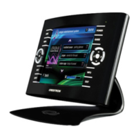
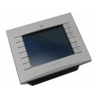
Crestron Isys™ TPS-6000 15 Inch Tilt Touchpanel
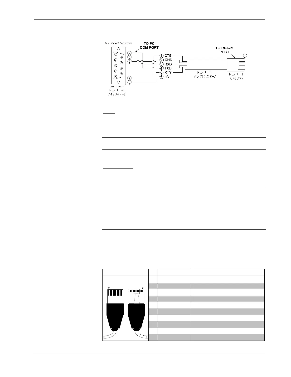
PC to TPS-6000 Cable Specifications (Crestron Cable Number STCP-502PC)
RGB
This port is blank until the TPS-XVGA expansion card is purchased and installed.
Consult the latest revision of the TPS-XVGA Operations & Installation Guide (Doc.
5868) for details.
NOTE: RGB connector is only available after installing the expansion card into the
TPS-6000 touchpanel.
NET/VIDEO
This 10-pin RJ-45 connector mates with the TPS-IMPC or TPS-IMW interface
module and has a dual purpose.
CAUTION: The 15-foot, 10-pin RJ-45 connector cable supplied by Crestron is a
custom cable and is the only one that should be used. The end of the cable has a
metal shield that is required to protect the equipment. Using non-Crestron cables will
result in damage to the product. Other cable lengths are available from Crestron.
NOTE: When connecting the touchpanel to the interface module, do not confuse the
8-pin audio cable with the 10-pin net/video cable.
This 10-pin RJ-45 port provides network connection from the touchpanel to the
interface module and network power to the touchpanel. This port also contains the
composite and S-video connections if a TPS-VID-1 or TPS-VID-2 is installed in the
TPS-6000. Refer to the descriptions and pinout table that follow this paragraph.
Pin Assignments
TYPE PIN DESIGNATION DESCRIPTION
1 +24V Power (Network)
2 GND Ground (Network)
3 C+ Chrominance (Positive) /Composite 2
4 C- Chrominance (Negative) /Composite 2
5 Y Data (Network)
6 Z Data (Network)
7 Y+ Luminance (Positive)/Composite 1
8 Y- Luminance (Negative)/Composite 1
9 GND Ground (Network)
10-pin RJ-45
Pin 1
Pin 1
10 +24V Power (Network)
Operations Guide - DOC. 5864A 15 Inch Tilt Touchpanel: Crestron Isys™ TPS-6000 • 21
 Loading...