11
CroozerCargo14-ENG-2-14
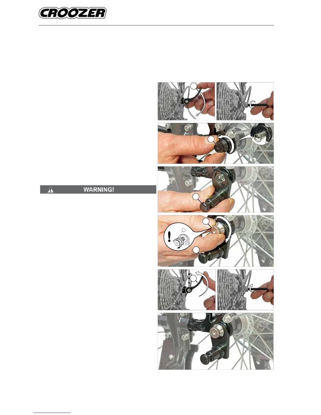
Converting the Croozer Cargo to a Bicycle Trailer
Installing the axle hitch to a bicycle with a quick-
release axle
The quick-release lever (1) must be positioned on the right
side of the bicycle (relative to the direction of travel). If the
lever is on the left side, the quick-release assembly must
be removed and reinserted from the right side. Be sure to
follow the applicable instructions in the owner’s manual of
the bicycle and/or consult a professional bicycle mechanic.
1. Disengage the quick-release lever (1) on the rear
wheel of the towing bicycle or loosen the hex bolt
(5 mm), depending on the version. Often, the open
position is indicated on the lever by the word “OPEN”.
In this case, when the word “OPEN” can be seen, the
lever is in the open position.
2. Remove the tension-adjusting nut (2) of the quick-
release assembly by turning the nut anticlockwise.
Use caution: the spring located just beneath the nut is
under tension and could y off when removing the nut.
3. Fit the axle hitch (3) over the end of the quick-release
skewer by sliding the skewer (with the spring) through
the hole in the hitch.
4. Without removing the spring on the end of the quick-
release skewer, thread the tension-adjusting nut (2)
back onto the skewer. Tighten the tension-adjusting
nut until you feel a slight resistance.
The tension-adjusting nut must engage the threads for at
least five full turns in order to ensure adequate clamping
force for holding the rear wheel securely. Failure to tighten
the tension-adjusting nut adequately may result in accidents
with serious injury or death. If the quick-release skewer is
too short, it must be replaced. Consult a professional bicycle
mechanic for the appropriate parts and assistance.
5. Check that the rear wheel is properly aligned, adjusting
the position if necessary; then close the quick-release
lever (1) or tighten the hex bolt, depending on the ver-
sion. Often, the closed position is indicated on the lever
by the word “CLOSE”. In this case, when the lever side
marked “CLOSE” can be seen, the lever is in the closed
position. If the tension-adjusting nut has been tightened
the proper amount, you will be able to feel the resist-
ance increase when the lever is about halfway closed,
i.e. parallel to the axle. The adjustment is correct if you
can fully close the lever but with considerable force. In
the closed position, the lever should be parallel to the
frame, i.e. it should not stick out to the side.
6. Check whether the quick-release is securely engaged
by trying to rotate the endcap of the mechanism
(where the lever is attached) without opening the lever.
If the endcap is loose enough to rotate, then the
clamping force is inadequate. In this case, open the
lever, and tighten the tension-adjusting nut half a turn
clockwise. Repeat steps 5 and 6.
If it is impossible to push the quick-release lever into
the closed position, then open the lever, and unscrew
the tension-adjusting nut half a turn anticlockwise.
Repeat steps 5 and 6. Keep in mind that the tension-
adjusting nut must engage the threads of the quick-
release skewer for at least ve full turns.
3
2
3
min. 5 x
1
2
1