Page 12
CDi DriveCore Series Operation Manual
Conguring the Amp
Configuring Inputs & Outputs
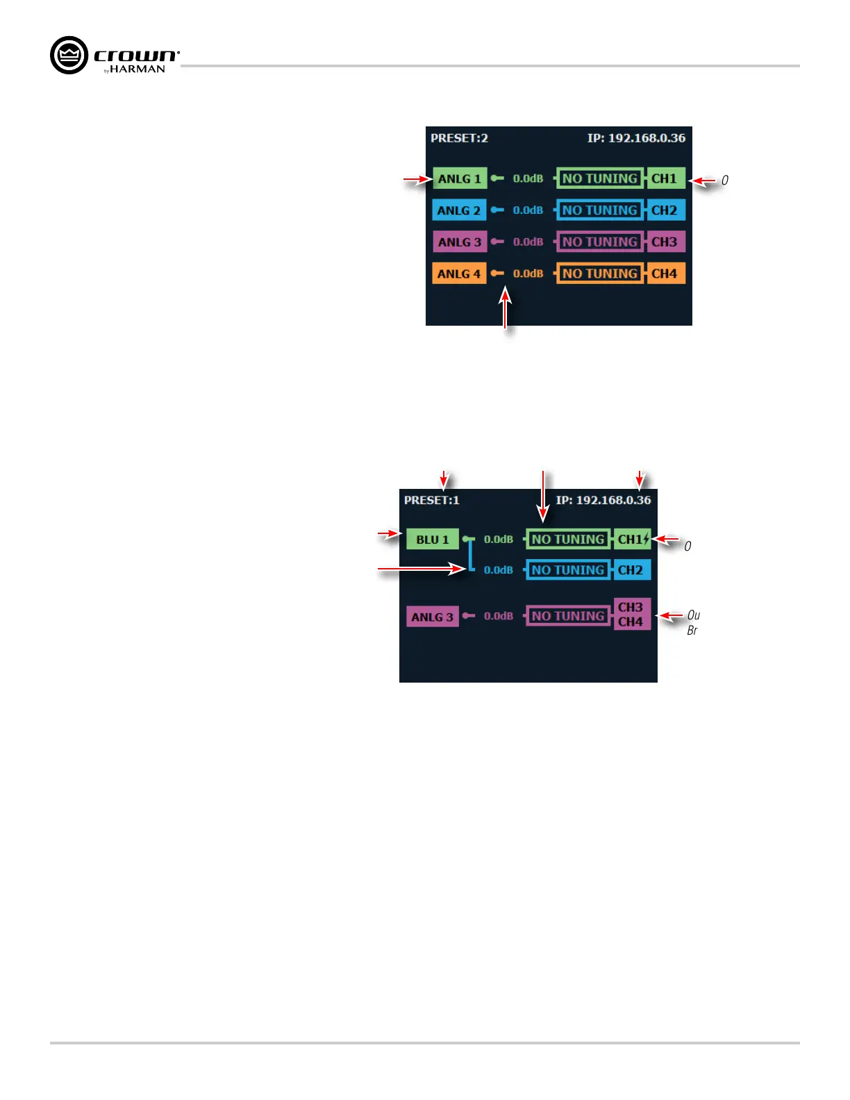
The CDi DriveCore amplifiers ship from the
factory with each output channel sourced
from its respective analog input (e.g., analog
input 1 goes to output 1, etc.), as shown in
Figure 11.
When viewing the Home screen, signal flow
is represented by lines that travel from the
input source (leftmost box) to the channel
output (rightmost box).
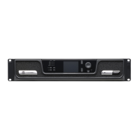
Additional amplifier configuration information
can be seen at-a-glance on the Home screen,
as shown in Figure 12.
Analog 1 Source Input
Channel Assignment
Signal Routing
Output Channel 1
Figure 11: Default CDi DriveCore configuration
Current Device Preset
Input Channel
Assignment
Signal Wiring
("Y'ed" inputs shown)
Lightning Bolt Indicates
Output Configured for
High Z Operation
Ganged Block Indicates
Output is Configured for
Bridge Mono Operation
IP Address
No Speaker
Tuning/DSP Used
Figure 12: CDi DriveCore configuration example viewed from the front panel Home screen