K Series Service Manual Rev A.
5-4 Maintenance
©1999 Crown International, Inc.
2. Remove the P2 ribbon cable from the Input PWA.
3. Using a needle nose pliers, unplug the six red wires
that go to the positive output binding posts. Note where
they go.
4. Using a TX15 bit, remove the three screws that se-
cure the Main PWA to the back panel.
Caution: Do not power up the amplifier without re-
placing these screws, or circuit damage to the Out-
put PWAs will occur.
5. Locate the plastic board stand–off between the Main
and Input PWAs. Using your fingernail or pliers, press
the release tab on the stand–off while gently separat-
ing the two PWAs.
6. Lift the Main PWA away from the back panel.
When installing the Main PWA onto the Back Panel
Assembly be careful not to bend the capacitor located
under the Line Filter PWA. If the unit is an early non-CE
unit, the clearance between a capacitor on the Line
Filter and a capacitor on the Main PWA is very small.
5.2.7 Output PWA Removal
The left and right Output PWAs are identical.
1. Follow the instructions in Section 5.2.2. Supply
discharge is necessary to avoid circuit damage.
2. Unplug the P01 ribbon connector and the P3 wiring
harness connector from the Output PWA.
3. Using a TX15 bit, remove the screw located at the
center–top of the assembly. See Figure 5.3.
Item A.
4. Using a TX20 bit, remove the six screws located by
the four large coils on the assembly. See Figure 5.3.
Item B
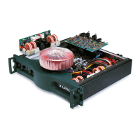
Figure 5.3 Output PWA Screws
Be very careful not to damage the coils with your screw-
driver. Note that the screws have belleville washers on
them. When replacing the screws be sure the cupped
side of the washer is down toward the assembly.
5. Carefully lift the assembly out of the chassis. When
reinstalling the Output Assembly use a new insulator
pad and make sure there are no metal shavings on the
pad or the heatsinks. Any metal shavings will result in
a “blow–up” when the unit is first turned on. To be sure
that the insulator is free of shavings, and is installed
correctly, use an Ohm Meter to check for continuity
between the assembly heatsink and the chassis. There
should be no continuity.
5.2.8 Control PWA Removal
1. Follow the instructions in Section 5.2.2. Supply
discharge is necessary to avoid circuit damage.
2. Remove EMC shield on all but early non-CE units.
3. While noting where each wire goes, disconnect each
connector on the Control PWA. The white wire goes on
P9, and the black wire on P8. The two orange wires go
on P10 and P11. The two purple wires go on P12 and
P13.
4. To remove the Bridge Rectifier (D1) along with the
PWA, use an
11
/
32
-inch (.86 cm) nut driver to remove
the nut. If you wish to leave the Bridge installed to the
chassis then desolder the four rectifier pads.
5. Using a TX15 bit, remove the three screws that hold
the Control PWA in place.
6. Lift the Control PWA out of the chassis.
If replacing the PWA with a new one, be sure and re-
move the Voltage Plug (P7) and install it on the new
PWA.
If replacing the Bridge Rectifier, be sure and use ther-
mal heatsink compound between the rectifier and the
chassis.
5.2.9 Line Filter PWA Removal (Early non-CE Units Only)
1. Follow the instructions in Section 5.2.2. Supply
discharge is necessary to avoid circuit damage.
2. While noting where each wire goes, disconnect each
wire from the PWA. The blue power cord wire goes on
P4. The long black wire goes on P1, the white on P2.
The short black wire from the fuse goes on P3.
3. Using a TX15 bit, remove the two screws that attach
the assembly to the back panel.
4. Lift the Line Filter PWA out of the chassis.
5.2.10 Power Transformer Removal
The Front Panel Assembly must be removed in order
to remove the Power Transformer.
1. Follow the instructions in Section 5.2.2. Supply
discharge is necessary to avoid circuit damage.
A
B
B