K Series Service ManualRev A.
Exploded View Parts 7-3
©1999 Crown International, Inc.
Description Part # (CPN) Qty. Notes
Chassis 102226-X 1
Front Panel Assembly — 1 See 6.4
Back Panel Assembly — 1 See 6.5
Bottom Cover 102076-X 1
Control PWA — 1 See Sect. 7
Output PWA — 2 See Sect. 7
Screw, 8-32 X .812 T20 A12148-70813 12
Rear Support 100848-X 2
Insulator, Output PWA 100536-X 2
#6 Internal Star Washer, Black A10094-3 7
#8 Belleville Washer A10098-3 13
8-32 Hex Nut A10102-6 1
Screw, 6-32X.375 Pan HD T15 A12148-70606 7
5.5" Cable Tie C 8812-7 3
35A 400V Bridge, Wire Lead C10246-4 1 At Control PCA
Screw, 8-32X.5 Flt Hd T15 100331-70808 18 Cover
Screw, 8-32X.312 Flt Hd T15 100331-70805 5 Top Rear
Screw, 8-32X.5 Flt Hd T15 101087-70808 8
Lockwasher, CSK Ext Tooth #8 101357-1 31
Wire, Pwr Switch Violet A11569-E160F 2
Wire Pwr Switch Orange A12122-C140D 2
Main Wiring Harness 101838-1 1
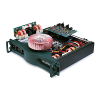
7.2 Main Chassis Assembly
Refer to figure 7.1 for Location of Major Parts
Front Panel to
Chassis
101528-1 1
Early non-CE
Models Only