Cryo-con Model 24C Specifications, Features and Functions
Control Loop Outputs
Control Loop #1, Primary Heater Output
The Loop #1 heater output is a short circuit protected linear current source. This
output is heavily regulated and RFI filtered. External filters should not be necessary.
Automatic shutdown circuitry is provided that will protect the heater output stage from
excessive temperature. Here, the heater output will be turned off until the output
stage returns to its safe operating area, then the output will be returned to normal
operation.
Load resistance values of either 25 or 50 may be selected. Using a 25 load, the
heater will be automatically configured to have a compliance voltage of 25V. With a
50 load, the compliance voltage is 50V. In either case, the maximum output current
is 1.0A.
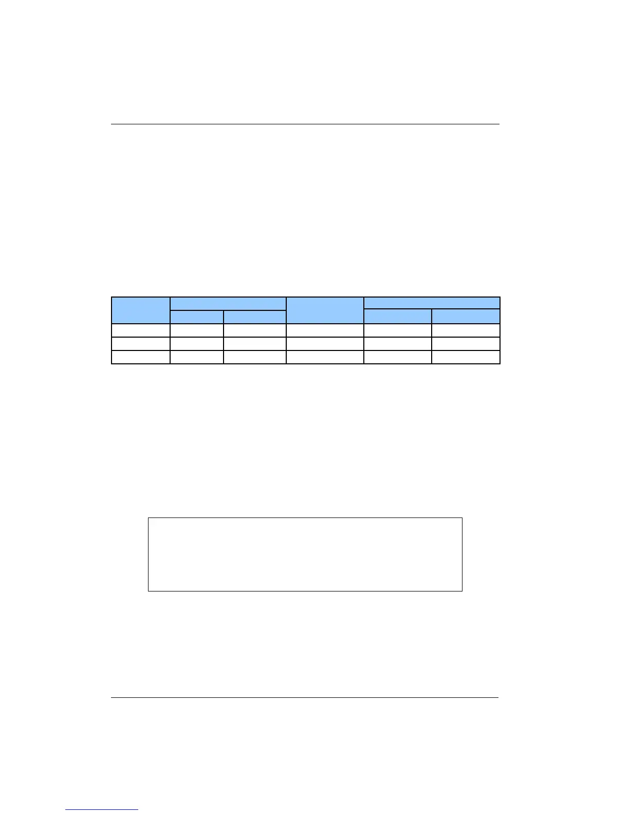
Range
Compliance Voltage
25 50
Full-Scale
Current
Max. Output Power
25 50
High
25V 50V 1.0A 25 Watts 50 Watts
Medium
25V 50V 0.333A 2.5 Watts 5.0 Watts
Low
25V 50V 0.100A 0.25 Watts 0.50 Watts
Table 12: Loop 1 Heater output ranges.
Take care to ensure that the proper load resistance is selected. Connection to a 25
load while a 50 is selected will result in overheating and eventual automatic heater
shutdown. Conversely, connection to a 50 load while setting a 25 load will result in
the dissipation of only one half of the indicated heater power in the load.
Load resistance and Full Scale Output Range are selected via the front panel, or any
of the remote interfaces.
Heater output power displays are based on the heater read-back circuitry which
measures output current independently of the actual heater circuitry. Thus, heater
fault conditions are detected and their corresponding alarms asserted.
i Note: Heater output displays are given as a percentage of
output power, not output current. In order to compute actual output
power, multiply this percentage by the full-scale power of the
selected range. However, to compute actual output current, you
must first take the square root of the percentage and then multiply
by the full-scale current.
34