Cryo-con Model 24C Appendix H: Rear Panel Connections
Appendix H: Rear Panel Connections
Sensor Connections
All sensor connections are made at the rear panel of the Model 24C using the two
DIN-6 receptacles provided.
Silicon diode and all resistor type sensors should be connected to the Model 24C
using the four-wire method. It is strongly recommended that sensors be connected
using shielded, twisted pair wire. Wires are connected as shown below and the shield
should be connected to the metal back-shell of the connector.
Pin Function
1
Excitation (-), I-
2
Sense (-), V-
3
Aux Power: +5VDC @ 500mA
4
Sense (+), V+
5
Excitation (+), I+
6
Not Connected
Table 38: Input Connector Pin-out
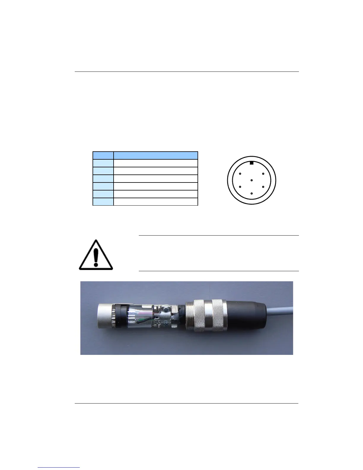
Caution: To ensure proper low noise operation, cable shields
should be connected to the metal back-shell of the
connector. A metal clip is provided with the connector for this
purpose. Please refer to the section on shielding and
grounding for further information.
Figure 7: Proper Assembly of the Input Connector
181