4. General
4.1 Guide to components
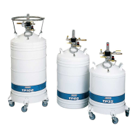
This illustration shows the main parts, both included
ones and options that make up a storage tank in the
TP
product line. These are described in greater detail
in the following paragraphs and pages. The tanks will
be used in an appropriate environment.
Figure 4-1: General view of the parts of a type TP storage tank.
4.2 Function
Cryogenic containers in the
TP
range are self-
pressurizing aluminium storage tanks for storing and
withdrawing liquid nitrogen at low pressures. A float-
type level indicator enables the amount of available
liquid to be checked. The removable control head is
fitted with a pressure gauge and two safety valves.
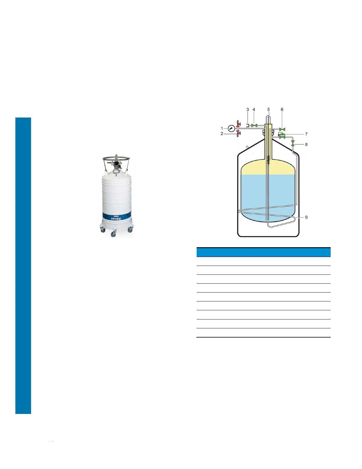
4.3 Principle
The storage tank contains liquid nitrogen. It is
pressurised by means of an exchanger (9) [regulating
valve (7) and shutoff valve (8)] located between the
walls. This exchanger vaporises liquid gas and thus
ensures that the tank is pressurised. The pressure
can be read off the pressure gauge (1). Two safety
valves (2) calibrated to 0.5 bars protect the tank. It is
filled via the connector (3) and valve (4) assembly.
Figure 4-2: Principle.
Ref. Designation
1. Internal pressure gauge.
2. Safety valves.
3. Connector (filling/withdrawing)
4. Filling and withdrawing valve.
5. Mechanical level indicator.
6. Venting /overflow valve.
7. Internal pressure regulating valve.
8. Pressure-building valve.
9. Pressure-building coil.