5. Description
This section describes the two main parts, i.e. the
storage tank and the control head.
5.1 Storage tank
The self-pressurizing aluminium storage tank enables
liquid nitrogen to be stored and withdrawn. It consists
of the following parts:
A tank (6) consisting of two aluminium alloy
enclosures connected by a collar of composite
materials. It is thermally insulated by means of a
vacuum between the two annular spaces and
several layers of insulation on the internal
container. The exterior of the tank is coated with
polyurethane paint for a good finish and durability.
A flange head DN50 (3), onto which the control
head is fastened (see next section).
Two handles (5).
A vacuum valve (7) which also acts to keep the
annular spaces safe.
A controller (2) intended to control the tank's once
the installed control head and the pressure-
building valve (1) have been opened. The basic
setting is 0.5 bar.
A pressure-building heating coil (4).
An insulating, enclosing stopper (8) that limits
nitrogen loss. This stopper must be placed on the
flange whenever the control head is not fitted on
the tank.
The neck of the tank must never be
hermetically sealed.
Two self-adhesive labels carrying warnings and
product identification.
Refer to:
On page 12 for details of how these components
operate.
On page 34 for the technical specifications of the
various models.
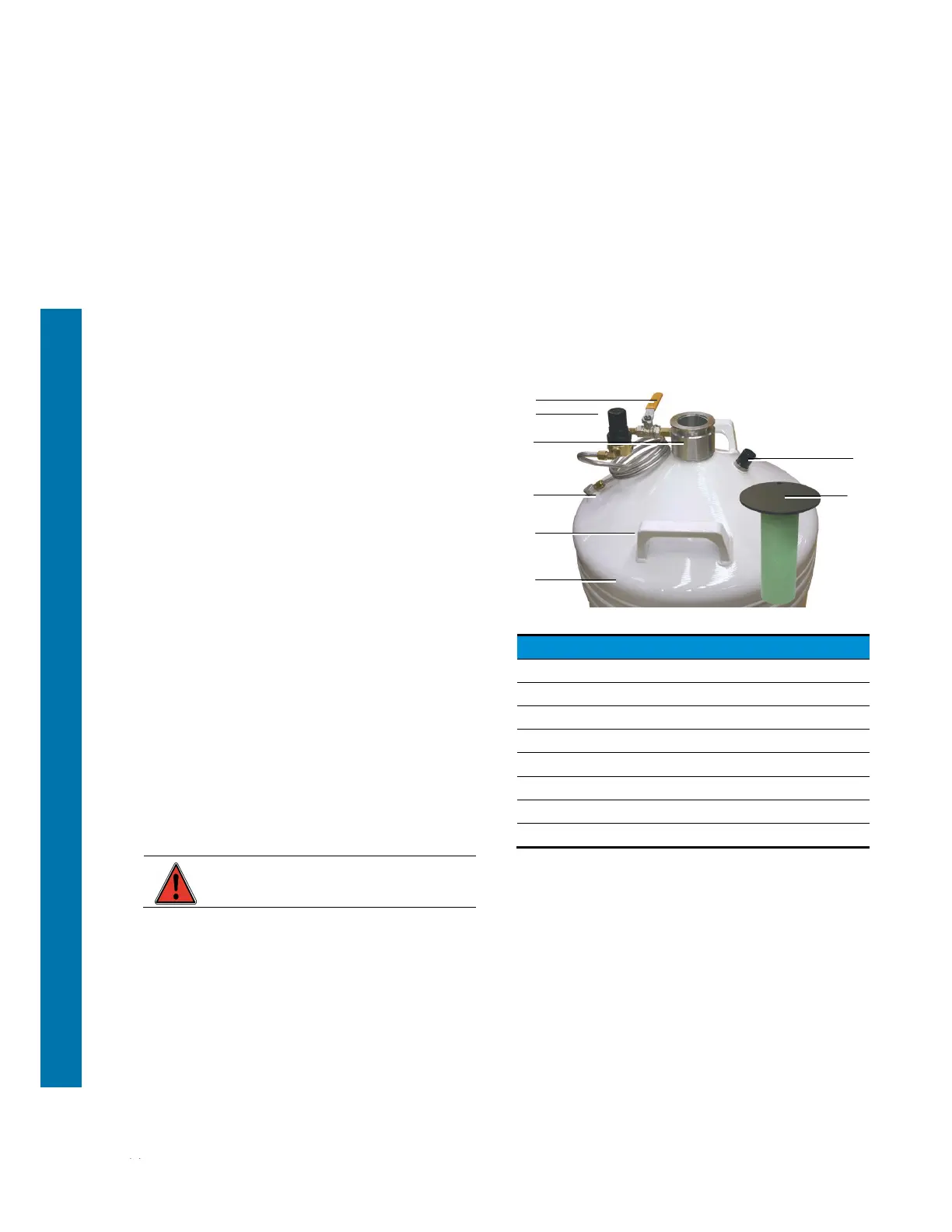
Figure 5-1: Overview of the tank
Ref. Function
1. Pressure-building valve.
2. Controller.
3. Head flange, nom. dia. 50 mm
4. Heating coil.
5. Handle
6. Tank.
7. Annular space safety device.
8. Stopper.
1
2
3
4
5
6
7
8