2. Remove the control head. Refer to section 7.2, on
page 21.
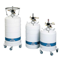
3. Once the assembly has warmed up to room
temperature, check that the stem (2) slides
smoothly along the indicator (1).
By grasping the float and sliding the stem between
the very bottom line and the very top line of the
indicator.
If it catches on anything, replace the assembly.
Adjusting the level indicator is covered in section
9.4, on page 29.
9.3.4 Inspecting for leaks
This must be checked every year. The required tools
are as follows:
A mixture of soap and water in a beaker.
A brush.
Proceed as follows:
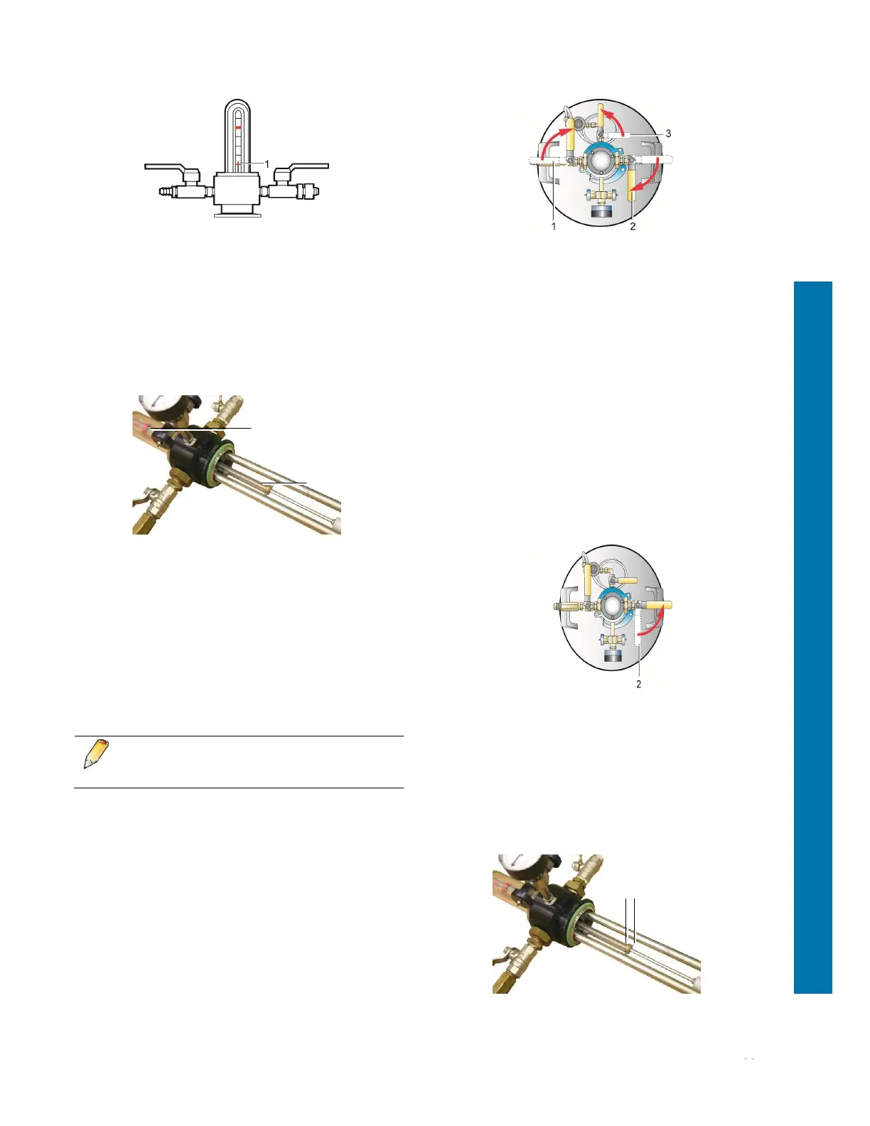
The control head is mounted on a tank and
the tank is considered to be full of liquid
nitrogen.
1. Check that the vent valve (2) and the
filling/withdrawal valve (1) are closed.
Open the pressure-building valve (3) and wait for
the tank's pressure to rise to 0.5 bars.
2. Using the brush, dab soapy water over the various
connections. If bubbles appear, this indicates a
leak. If a leak is observed, renew the seal on the
connection concerned.
9.4 Adjusting the level indicator
This becomes necessary after the equipment has
been roughly handled or following successive fitting
and removal of the control head.
9.4.1 Adjusting the zero mark
This procedure consists of making the red ring on the
stem coincide with the zero marker engraved on the
transparent cap. Proceed as follows:
1. Open the vent valve (1) to release any pressure.
2. Remove the control head (§ 7.2, page 21) and wait
for it to warm up.
3. Using a 2 mm hexagon key, unscrew the hex
socket grub screw (4) so that the ring (3) slides up
and down the stem.
2
1
3 4