4. Place the ring (3) at the correct height and tighten
the grub screw (4) again to immobilise the ring.
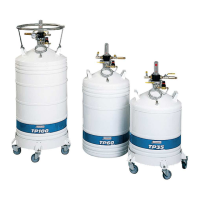
Thus the more the spring is stretched (ring
displaced towards the float) the higher the red
mark rises (5).
The correct height is reached when the top end of
the end mark is at the very last line on the indicator
(6) with the control head vertical.
9.4.2 Adjusting the position of the red ring
on the stem
This procedure consists in positioning the red ring on
the stem. The red ring may have slipped along the
stem (1 in the above figure). Its normal position is a
few millimetres from the stem. Proceed as follows:
1. Undo the grub screw to release the ring (1) from
the stem (2).
2. Slide the ring (1) until the red marker (3) is
accessible and reposition the marker by sliding it
along the stem.
3. Adjust the ring as shown in section 9.4.1.
If the above actions do not allow the level to
be adjusted, the spring must have been
damaged by bad handling. In this case, the
control head assembly must be replaced.
9.5 Changing components
Before replacing any components the tank
must be emptied and brought to room
temperature.
9.5.1 Changing the gauge-and-valves
assembly
Proceed as follows:
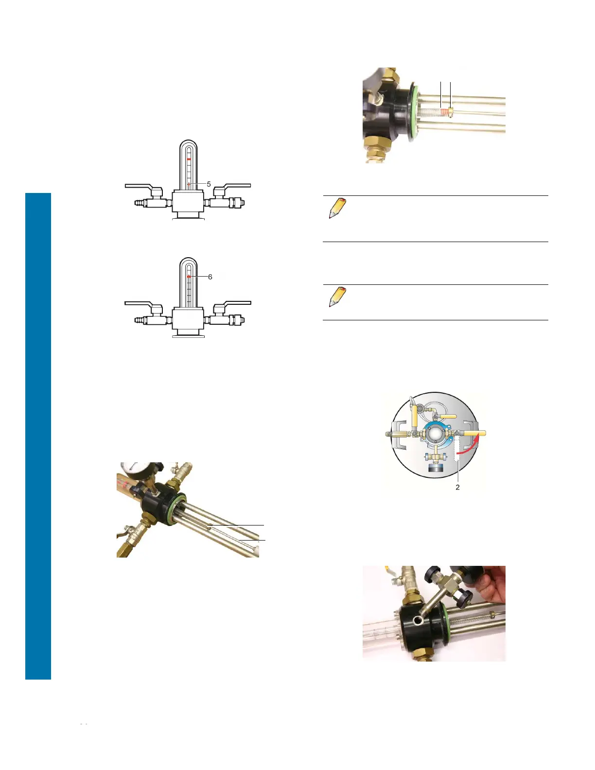
1. Open the vent valve (1) to release any pressure.
2. Withdraw the pressure gauge and safety valve
assembly, taking care not to unscrew any other
parts of the control head and carefully clean the
internal screw threads so that all traces of joint
filler are removed.
1
2
3 1