FRM220 Chassis Quick Installation Guide
17
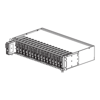
Panels
Figure. Front Panel
Note: For Telnet, Web, Console and SNMP management, NMC
card must be inserted in Slot 2.
Figure. Rear Panel
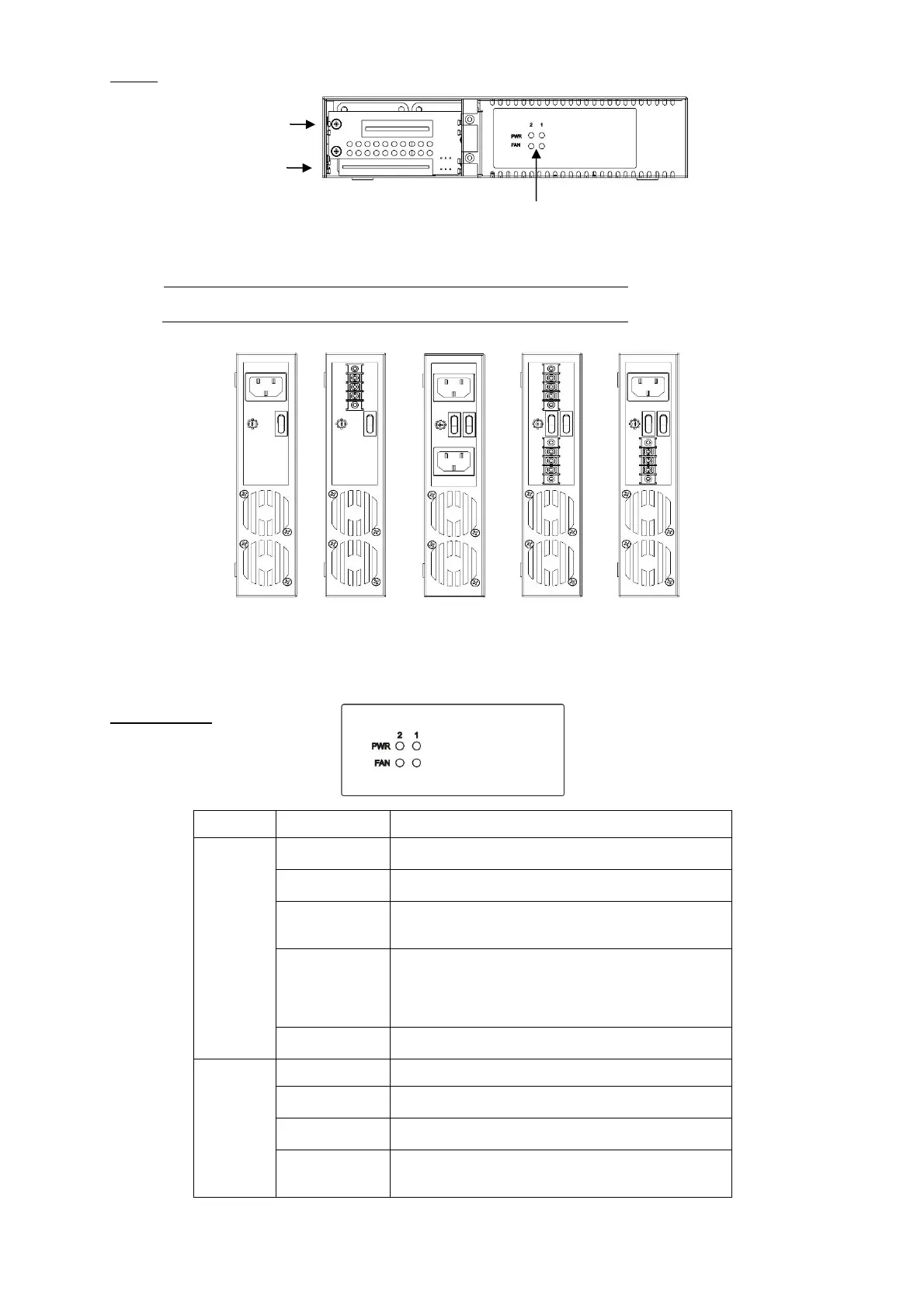
LED Indicators
The chassis receives power current from power
1 or 2.
Power current is zero (in standby mode).
Power voltage is smaller than 9V or power
current is over 2500 mA.
(Voltage < 9V or Current > 2500 mA)
Power voltage is larger than 10.5V but smaller
than 9V or power current is larger than "2500 *
90% mA" but smaller than 2500 mA.
(10.5V < Voltage < 9V or 2500 * 90% mA <
Current < 2500 mA)
Turn off the PWR 1 or 2 LED indicator via the
NMC card.
Current fan speed (RPM) is slow than "fan
speed * 60%".
Current fan speed (RPM) is slow than "fan
speed * 20%.
- Power current is smaller than 300 mA. (in Auto
Sensor mode)
- Fan is off or not working.
Power & FAN
LED Indicators
 Loading...