FRM220 Chassis Quick Installation Guide
30
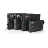
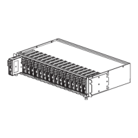
Power/Fan Modules Removal/Replacement
The Power Supply Modules in CH08 are available in three versions, one AC and two DC types. The
universal AC version supports input voltages of 100 to 240 (±10% @ ambient temperature) volts at
frequencies of 47 to 63 Hertz. The DC versions support an input range of either 36 to 60VDC or 18 to
36VDC. Only one power supply module is required to power a completely full rack. When two Power
Supply Modules are installed, the supplies are hot swappable and redundant, meaning any one supply
may be removed and replaced without impacting the operation of CH08 Rack. If the chassis will be used
to power 3R transponder cards such as the 2.7G and 10G, the chassis will require two power/fan
modules or overheating could result.
Figure. Power Modules for CH08
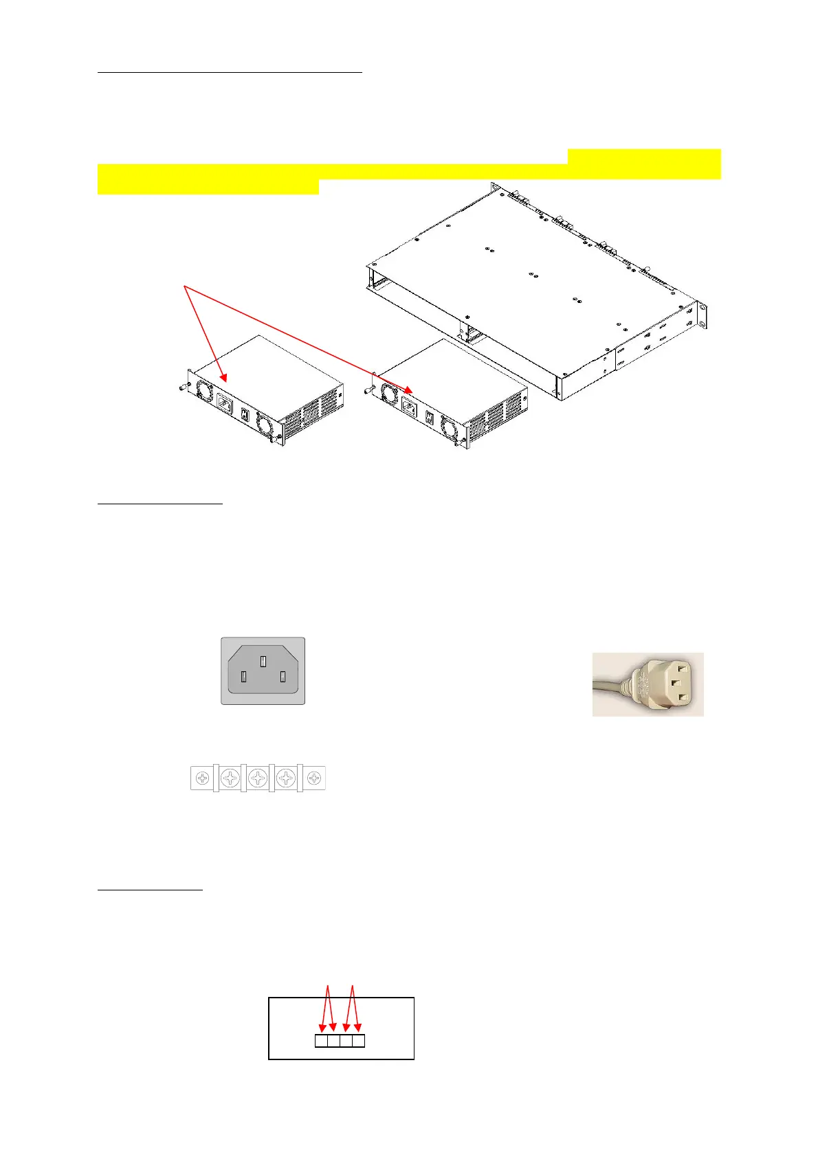
Electrical Installation
With an AC power module, AC power is supplied to CH08 through a standard IEC C14 3-prong
receptacle, located on the rear of the module. Any national power cord with IEC C13 line plug may be
used to connect AC power to the power module. With a DC24 or DC48 module, DC voltage is connected
to the terminal block located on the rear of the module, observing the proper polarity. CH08 should
always be grounded through the protective earth lead of the power cable in AC installations, or via the
frame ground connection for DC installations.
Figure. IEC (AC) & terminal block (DC) power connector pin assignment
Alarm Installation
The alarm relay provides one set of Power Failure contacts (normally open) and another set of FAN
Failure contacts (normally open) contacts for monitoring the power and fans condition of CH08. The
alarm contacts may also be programmed through the management interface to react to different fault
conditions.
Figure. Alarm Relay Contacts
 Loading...