CTI 2572-B / 2500C-2572-B Installation and Operation Manual 25
The S
OURCE ELEMENT specifies the 505 PLC Tag Name. We want to read a 16 bit unsigned integer into a 32 bit
signed Control Logix tag, so we will use the tag type VE. Since we want to start reading at V memory location
501, the complete Tag Name is VE501.
We want to read a block of 100 registers, so the N
UMBER OF ELEMENTS will be set to 100.
The D
ESTINATION ELEMENT specifies the Control Logix tag that will store the results of the read message. This is
the tag we defined earlier. Since this is an array, we will specify that first value returned will be stored in array
element 0. Additional values will be stored in subsequent array elements.
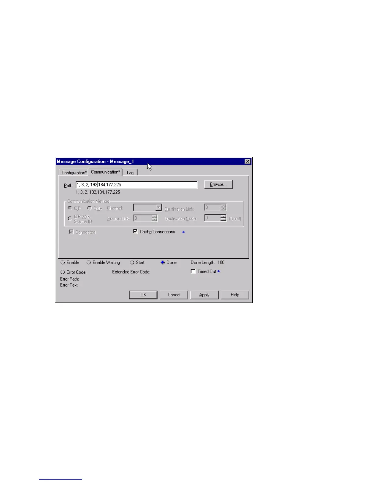
Communication Tab
The Communication Tab is used to specify the message routing and destination IP address.
The path specifies the route from the controller to the destination. In this case, we will send the message to
the backplane (1), to the Ethernet module located in slot 3, out the Ethernet port (2), to the 2572-B module
whose IP address is 192.184.177.225.
The C
ACHE CONNECTIONS box is checked to keep the TCP connection established after the message is completed.
If you don’t check this box, the Control Logix will close the TCP connection after each message transaction is
complete. Continually opening and closing the TCP connection adds unnecessary overhead and reduces
performance.
 Loading...