2-13 Boot To Mower Deck Installation
Continued
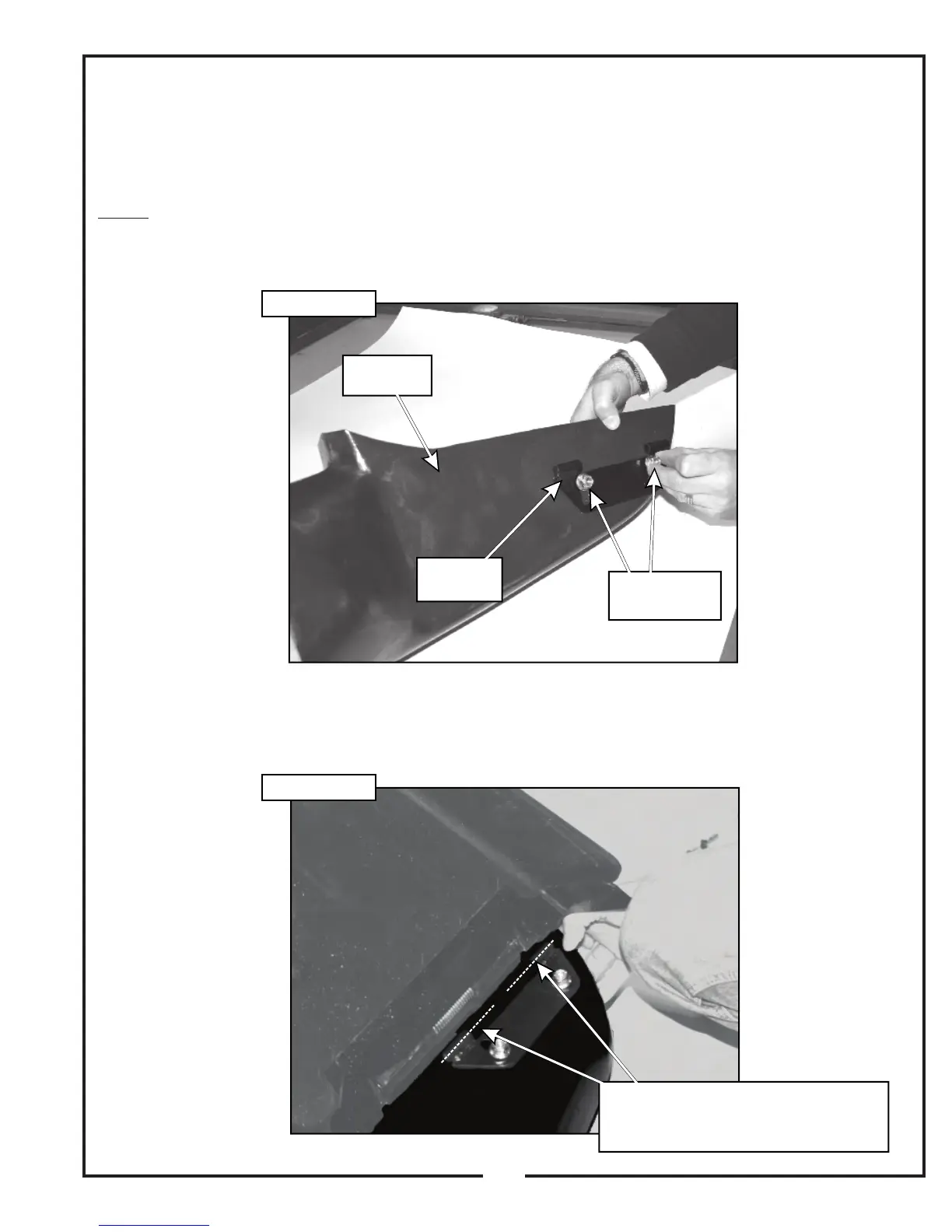
Step 9: Locate the aluminum boot P#(E0020) and the
boot plate assembly P#(A1121). Secure the boot plate
assembly to the boot as shown in Figure 2-13k, using (2)
3/8”-16 x 1” carriage bolts P#(K1182) and (2) 3/8”-16
nylon flange locknuts P#(K2038).
NOTE: Insert the carriage bolts from inside of the boot
so that the threads are on top of the boot as shown in
Figure 2-13k. This will prevent grass clipping from
collecting on the bolt threads. DO NOT TIGHTEN THE
HARDWARE.
Step 10: Lift the discharge chute on the mower deck and
position the boot assembly as shown in Figure 2-13l.
Align the bushings on the boot plate assembly with the
bushings on the deck mount plate.
Aluminum
Boot
Align The Bushing On The
Deck Mount Plate With The
Bushings On The Boot Plate Assembly
Boot Plate
Assembly
Nuts Fasten
From The Top
21
Figure 2-13k
Figure 2-13l
 Loading...