2 Inspection and Adjustment
11
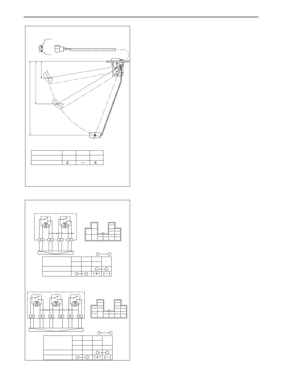
6 Fuel Gauge
Using the circuit tester, make sure that resistant value
between terminals for the fuel gauge becomes as shown
in the figure.
• If the resistant value is not as shown in the figure,
change the fuel gauge.
7Relay
Step 1: Using the circuit tester, make sure that resistant
value between terminals for the relay becomes as shown
in the figure.
Step 2: Connect 12V to the terminal.
Using the circuit tester, make sure that resistant value
between terminals for the relay becomes as shown in the
figure.
• If the resistant value is not as shown in the figure,
change the relay.
241.7 {9.52}
138.7{5.46}
53 {2.09}
F
B
YR
E
1/2
(Unit: Ω)
Float Position F
3 (32.5) 110
2
7
E1/2
Resistant Value
Tolerable
(mm {in})
GZ3W41-014
LYPW
GY
W
1A 1A
B
LW
L
Y
PW
GY
W
B
LW
1
2
LY
WGYLW
PW
B
HST Specification
Manual Specification
Step
Key switch
(LOAD)
1
2
LY
WGYLW
OLGGW
PW
B
BrB
Step
a
a
b
b
c
c
i
i
kl
l
d
d
j
j
LYPW
GY
W
B
LW
a
b
c
i
O
m
LG
p
GW
n
BrB
o
l
d
j
Lamp
Key switch
(LOAD)
Lamp IND PTO
L
Y
PW
GY
O
GW
BrB
LG
W
B
LW
a
b
c
ikl
d
j
mn o p
Continuity:
Continuity:
GZ3W41-015
www.mymowerparts.com
K&T Saw Shop 606-678-9623 or 606-561-4983

 Loading...