Domestic Series 7000 Damped Driveshaft
70
2.3. Slide the back end of the driveshaft off of the
splined input shaft on the hydrostatic drive, and
remove the driveshaft.
NOTE: The original driveshaft is a two-piece
assembly. At the technician’s discretion, it may
be removed intact, or separated then removed.
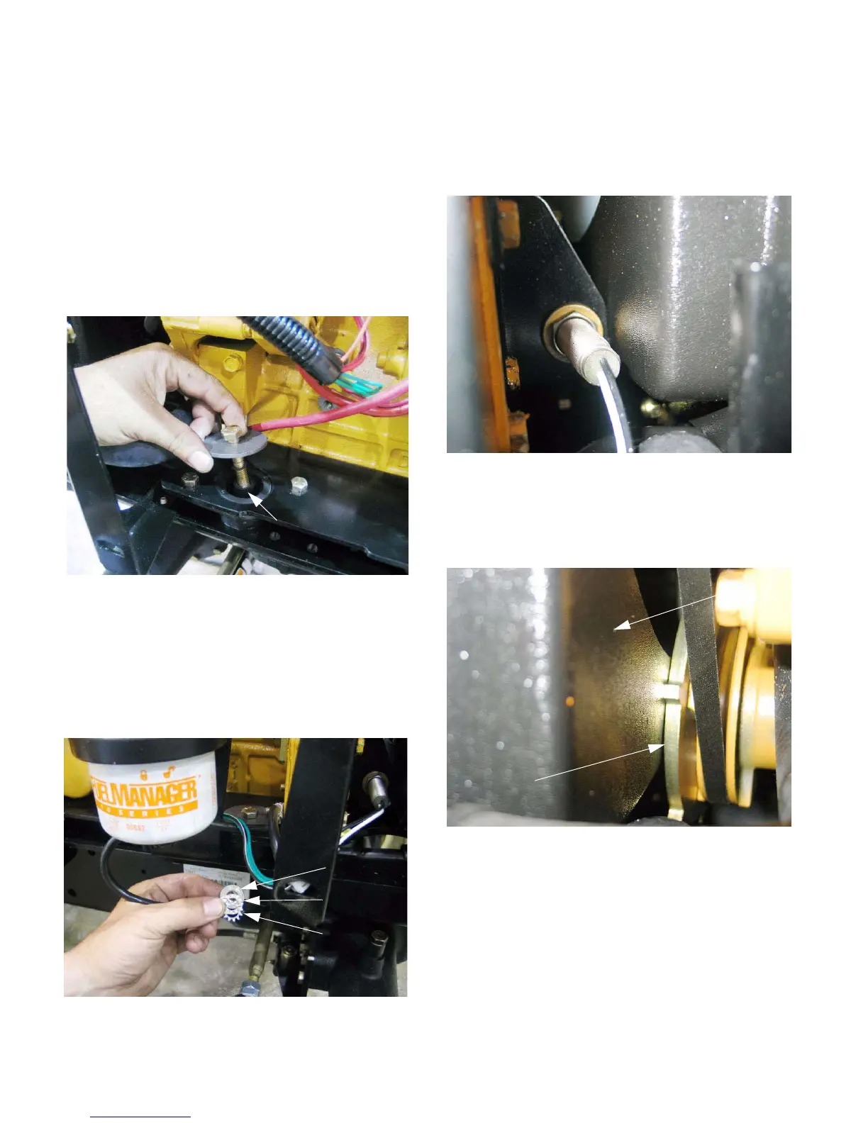
2.4. Remove the four bolts, nuts, and large flat wash-
ers that are used to secure the engine compres-
sion mounts to the tractor frame. This can be
done using a pair of 9/16” wrenches.
See Figure 2.4.
2.5. Of the four bolts, the one at the right front corner
of the engine also holds the negative battery
cable. The cable will come off when the nut is
removed, and there is a star-type lock-washer
between the cable eyelet and the frame to
ensure good electrical contact. See Figure 2.5.
2.6. Slide the engine as far forward as possible. The
left side of the engine goes slightly farther than
the right side because of interference between
the engine speed sensor and the fan shroud on
the right side. See Figure 2.6.
2.7. On the left side, the engine can be pushed for-
ward until the engine RPM plate (tone ring)
nearly touches the fan shroud. See Figure 2.7.
2.8. Apply a small amount of anti-seize compound to
the splined input shaft on the hydrostatic drive.
2.9. Apply a small amount of threadlocking com-
pound such as Loctite 242 (blue) to the clean
threads of the three bolts that hold the flange on
the front to the replacement driveshaft to the fly-
wheel.
Figure 2.4
Compression
mount
Figure 2.5
Nut
Cable eyelet
Star washer
Figure 2.6
Figure 2.7
RPM plate
Fan
shroud

 Loading...