Domestic Series 7000 Damped Driveshaft
71
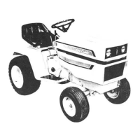
2.10. Slide the replacement driveshaft into position.
the flange should nest into the recess in the fly-
wheel.
2.11. Fasten the driveshaft to the flywheel using the
three loctited bolts with hardened washers.
2.12. Slip the back end of the driveshaft onto the
splined input shaft on the hydrostatic drive.
See Figure 2.12.
2.13. Slide the engine back into position, so that the
mounting holes in the frame align with the holes
in the engine compression mounts.
NOTE: This will bring the rear yoke on the drive-
shaft into full engagement on the splines of the
hydrostatic drive.
Figure 2.10
Flywheel
Drive flange
Inset: bolts and
hardened washers
Figure 2.12
Splined input
shaft
2.14. Prevent the flywheel from turning using a fly-
wheel tool or by blocking the driveshaft, and
tighten the flange-to-flywheel bolts to a torque of
27-33 ft.-lbs (37-45 Nm).
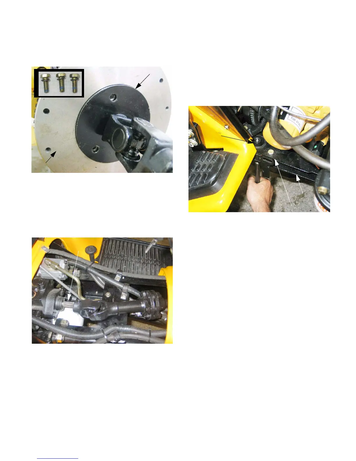
2.15. Make the final alignment of the engine so that
the engine mount bolts can be installed. A
tapered alignment pin is extremely useful for
this. See Figure 2.15.
2.16. Secure the engine compression mounts to the
frame using the nuts, bolts, and large flat wash-
ers previously removed. Tighten the nuts to a
torque of 23-31 ft.-lbs (31-40 Nm).
NOTE: If the locking feature on the nuts has
worn and they turn easily, replace them with new
ones, or apply a small amount of threadlocking
compound such as loctite 242 (blue) to the
threads.
NOTE: Do not forget the ground cable and star-
type lock washer on the right front mounting bolt.
2.17. Install the new fender cover that provides addi-
tional clearance for the flexible coupling on the
new driveshaft.
2.18. Connect the negative battery cable to the bat-
tery.
2.19. Install the over-flow bottle and hose.
2.20. Install the engine compartment side covers.
2.21. Close the hood.
2.22. Run and test the tractor in a safe area before
returning it to service.
Figure 2.15
Frame
Engine bracket
Compression
mount

 Loading...