7
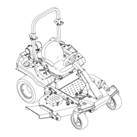
2-3 Lower Main Frame Installation
Secure the lower main frame P#(B0821) to the left rear frame of the
mower using (4) 3/8”-16 x 1” carriage bolts P#(K1182) and (4) 3/8”-
16 nylon flange locknuts P#(K2038). Leave the hardware loose.
Secure the lower main frame to the PTO mount plate assembly
using (2) 3/8”-16 x 1” carriage bolts P#(K1182) and (2) 3/8”-16 nylon
flange locknuts P#(K2038). Align lower main frame and PTO mount
assembly to be parallel and level to the mower’s chassis, then
tighten all hardware from Sections 2-2 and 2-3 at this time. Refer to
Figure 2-3.
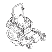
Secure the PTO mount plate assembly P#(A1108) to the chassis of
the mower using (4) 3/8”-16 x 1” carriage bolts P#(K1182) and (4)
3/8-16 nylon flange locknuts P#(K2038). Leave the hardware loose
until the lower mount assembly is installed in the next section. Refer
to Figure 2-2.
2-2 PTO Mount Plate Assembly Installation
(4) 3/8”-16 x 1”
Carriage Bolts
(4) 3/8”-16
Locknuts
Figure 2-2
PTO Mount
Plate Assembly
Figure 2-3
PTO Mount
Plate Assembly
Lower Main
Frame
(4) 3/8”-16 x 1”
Carriage Bolts
(4) 3/8”-16
Locknuts
(2) 3/8”-16
Locknuts
(2) 3/8”-16 x 1”
Carriage Bolts
Mower’s
Chassis
 Loading...