4
the kitchen faucet and allow all water to drain
from line.
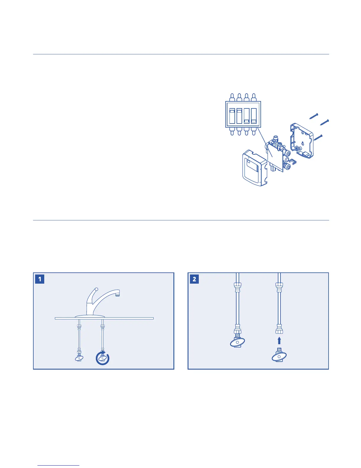
SETTING CAPACITY AND TDS FUNCTION
NOTE: Set capacity and TDS function before starting installation.
NOTE: To access the dip switches for setting capacity and TDS function,
open the control box by removing the three screws in the rear cover.
Find the dip switches on the front of the circuit board.
SW2 and SW3 set the time and capacity for the lter reminder.
SW2: OFF = 500 gallons ON = 1000 gallons
SW3: OFF = 180 days ON = 365 days
The system will measure the dierence between the feed and product
water to determine if the RO is working.
SW1: OFF = Disabled ON = Enabled
SW6 is used for production testing and should be left in the o position.
INSTALLATION
NOTE: Refer to the manual provided with your filter/RO for installation
instructions specific to that system.
NOTE: Some installations may require adapters and ttings not included with
the product. Review the manual and your installation before beginning.
NOTE: Consult your local plumbing codes and install accordingly.
Disconnect the cold water line from the cold water
NOTE:
is used, you may need to shorten the pipe using
a hacksaw or pipe cutter to accommodate the
control box.
SW6
SW3
SW2
SW1
ON

 Loading...