8 Culligan® Series E2 Plus Reverse Osmosis
8 Cat. No. 01023094
Plumbing Installation
Refer to the appropriate hydraulic schematic/flow diagram on page 26 for further information.
Feed Water Connections
Connect pipe or tubing to the Feed water inlet. Observe the following:
1. To minimize pressure loss, the pipe or tubing size should be at least 3/4”.
2. Install optional pressure gauges (quantity = 2 of P/N D1006272) before and after the pre-filter to measure the
pressure differential across the filter cartridge.
3. Install a tee, with a shutoff valve on the branch, before the feed flow meter to provide a connection for introduc-
ing cleaning solutions.
4. If necessary, install a pressure regulator (100 psi upstream max. setting) in the inlet plumbing, to assure con-
stant pressure and to prevent harmonic vibration.
5. Install a shutoff valve in the inlet plumbing to simplify maintenance and service.
6. If the feed water can be used for a short period, install bypass plumbing around the unit.
Concentrate Water Connections
1. Direct 1/2" tubing to drain from the outlet of the unit.
2. To prevent siphoning of the water in the unit to drain, raise the concentrate plumbing above the level of the
modules and provide an anti-siphon loop.
WARNING! An air gap must be provided between the end of the concentrate tubing and the
drain to prevent back-siphoning of drain contents.
Product Water Connections
The product water exits on the pump side of the unit in either piping or tubing. Connect the product plumbing to the fitting
on the flow meter.
CAUTION! This unit produces high quality product water. This water can be contaminated by
plumbing following the unit or it can corrode the plumbing. Use only plumbing com-
ponents of inert material that are compatible with the application.
The connection of the main product plumbing to service plumbing will depend on how the product water will be stored.
CAUTION! Reverse osmosis elements will fail immediately if product water is allowed to flow
backward into the unit.
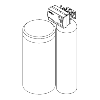
Pressurized Storage Tank
The product water can be stored in a pressurized storage tank with the reverse osmosis unit controlled by a pressure
switch. Use the same components used for direct feed (see Figure 5) with the addition of a pressure switch which needs
to be wired to the control panel (see page 27 for RO standard wiring). A pressurized water storage kit is available under
part number D1018976.