RO Installation 9
Cat. No. 01023094
Non-Pressurized Product Water Storage Tank
Connect the product tubing to a bulkhead fitting at the top of the storage tank.
CAUTION! The highest point of the tubing should not be higher than four feet above the top of
the reverse osmosis modules, or the elements may be damaged.
Depending on the type of application, a level control may be required to turn the unit off when the storage tank is full.
Install the level control according to the instructions provided with the control. Refer to the wiring section in this manual for
electrical connections.
NOTICE If a repressurization pump is used, an additional level control is recommended to prevent the
pump from running dry if the storage tank is empty.
To maintain high water quality, a hydrophilic air vent filter, vacuum breaker, pop-off valve, ultraviolet lamp, and pressure
relief valve may be required.
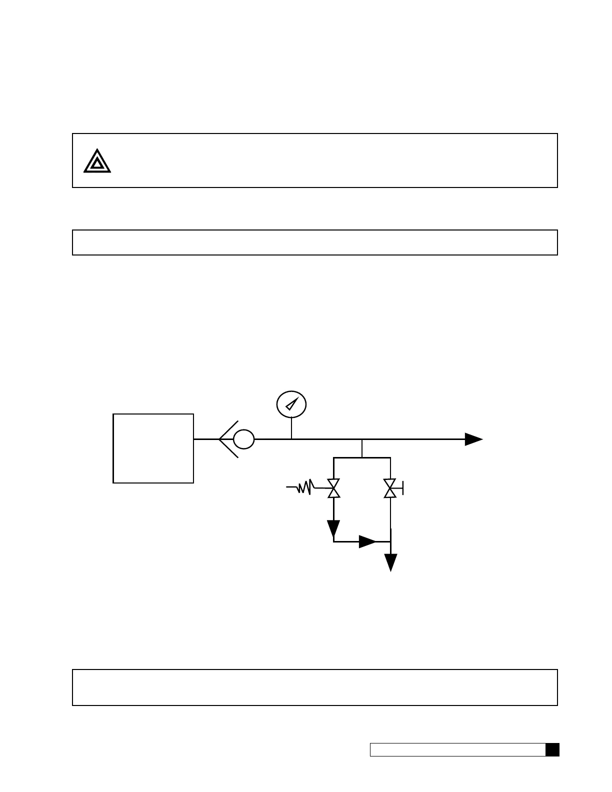
Direct Feed
If the product water is to be used directly, without storage, a few precautions are necessary to prevent damage to the
elements. Install a pressure gauge, pressure relief valve, and a normally-open (“dump”) solenoid in the product water line
as shown in Figure 5. The pressure gauge will allow the operator to monitor the product water pressure. The relief valve,
which should be set to open at 40 psig, will prevent the product water pressure from exceeding 40 psi. The dump solenoid
will relieve all pressure when the unit is off.
P/N 00440343
Reverse
Osmosis
System
Product Line
Pressure
Relief Valve
Solenoid
Valve
1
3
To Drain
To Service
Check Valve
Figure 5. Direct feed connection.
Wire the direct feed/pressurized storage solenoid valve in parallel with the motor.
NOTICE Install a check valve after these valves in case the service line remains under pressure. Product
back pressure will decrease the net pressure pushing water through the reverse osmosis ele-
ments. Therefore, the flow of product water will decrease.