24
01021076
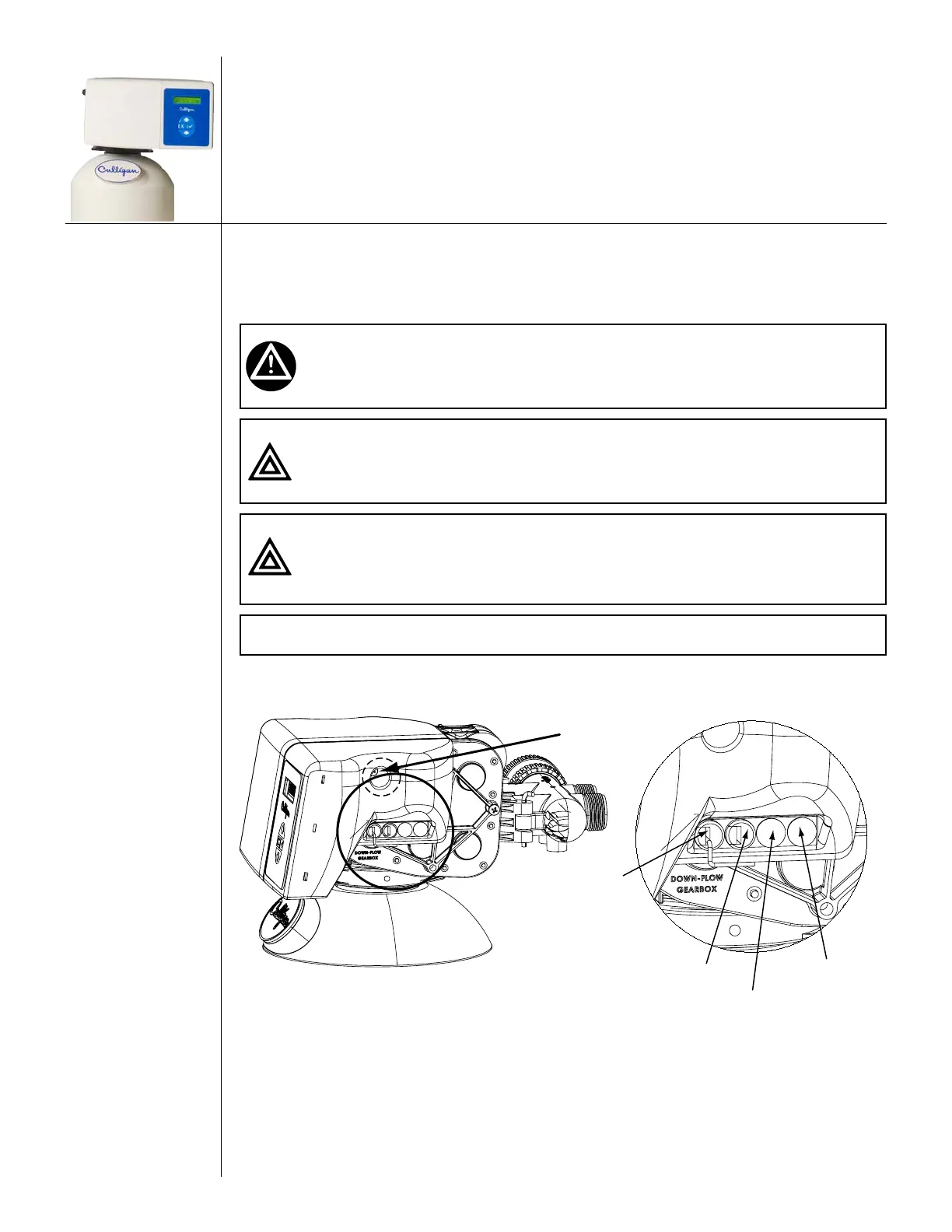
Circuit Board Connections
The 24 Volt power supply and flow meter wire harness is already connected to the circuit board. If no
other circuit board connections are required proceed to the First Time Setup. Refer to the instructions below
and Figure 19 to Figure 22 for connecting the Aqua-Sensor probe wire harness to the circuit board.
WARNING! Disconnect all electrical power to the unit before connecting.
CAUTION! Grip all connections to the circuit board by the connecting
terminals for assembly and disassembly. Failure to do so could
result in damage to the wire leads or connecting terminals.
CAUTION! Do not touch any surfaces of the circuit board. Electrical static
discharges might cause damage to the board. Handle the
circuit board by holding only the edges of the circuit board.
Mishandling of the circuit board will void the warranty.
NOTE Observe all state and local electrical codes.
1. Remove the electrical enclosure from the control valve. First remove the electrical enclosure
screw and then gently remove the enclosure from the control. Refer to Figure 19 and below
instructions.
24 Volt
Power Cord
Flow Meter
Wire Harness
Aqua-Sensor Wire Harness
and 2.5 Volt Power Cord
Accessories
Electrical
Enclosure Screw
Figure 19. Circuit board connections.
2. Remove the 24 Volt power supply wire harness from the circuit board. See Figure 20.
3. Grip the circuit board from the edges and gently rotate it to the back of the enclosure (you are
disengaging the circuit board from the two support pins on the bottom of the enclosure).
4. Remove the circuit board from the enclosure. See Figure 21.
5. Remove the plastic plugs from the enclosure.