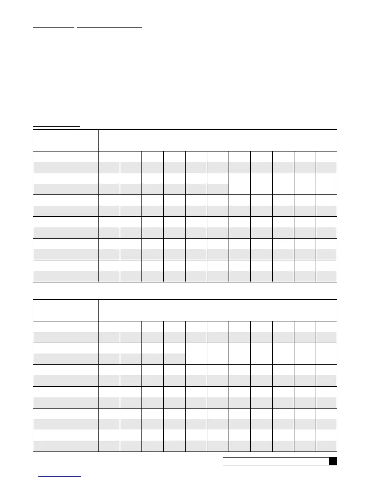
Average Water
Pressure
Height of Drain Discharge Above Floor Upon Which Softener Sets
psi 4 in. 1 ft 2 ft 3 ft 4 ft 5 ft 6 ft 7 ft 8 ft 9 ft 10 ft
kPa 0.1 m 0.3 m 0.6 m 0.9 m 1.2 m 1.5 m 1.8 m 2.1 m 2.4 m 2.7 m 3.1 m
30 56 50 40 30 20 10
2.1 17.1 15.3 12.2 9.2 6.1 3.1
50 112 106 96 86 76 66 56 46 36 26 16
3.5 34.2 32.3 29.3 26.2 23.2 20.1 17.1 14.0 11.0 7.9 4.9
70 143 137 127 117 107 97 87 77 67 57 47
4.8 43.6 41.8 38.7 35.7 32.6 29.6 26.5 23.5 20.4 17.4 14.3
90 153 147 137 127 117 107 97 87 77 67 57
6.2 46.7 44.8 41.8 38.7 35.7 32.6 29.6 26.5 23.5 20.4 17.4
120 159 153 143 133 123 113 103 93 83 73 63
8.3 48.5 46.7 43.6 40.6 37.5 34.5 31.4 38.4 25.3 22.3 19.2
Average Water
Pressure
Height of Drain Discharge Above Floor Upon Which Softener Sets
0.1 m 0.3 m 0.6 m 0.9 m 1.2 m 1.5 m 1.8 m 2.1 m 2.4 m 2.7 m 3.1 m
12-INCH MODELS
TABLE 1
9-INCH MODELS
psi 4 in. 1 ft 2 ft 3 ft 4 ft 5 ft 6 ft 7 ft 8 ft 9 ft 10 ft
kPa 0.1 m 0.3 m 0.6 m 0.9 m 1.2 m 1.5 m 1.8 m 2.1 m 2.4 m 2.7 m 3.1 m
30 44 38 28 18
2.1 13.4 11.6 8.5 5.5
50 103 97 87 77 67 57 47 37 27 17 7
3.5 31.4 29.6 26.5 23.5 20.4 17.4 14.3 11.3 8.2 5.2 2.1
70 129 123 113 103 93 83 73 63 53 43 33
4.8 39.3 37.5 34.5 31.4 28.4 25.3 22.3 19.2 16.2 13.1 10.1
90 145 139 129 119 109 99 89 79 69 59 49
6.2 44.2 42.4 39.3 36.3 33.2 30.2 27.1 24.1 21.0 18.0 14.9
120 153 147 137 127 117 107 97 87 77 67 57
8.3 46.7 44.8 41.8 38.7 35.7 32.6 29.6 26.5 23.5 20.4 17.4
INSTALLATION 9
SOFT-MINDER
®
METER CONNECTION
To connect the meter leads, refer to the instructions listed below and the wiring schematic.
• Remove the timer face plate & set it aside.
• Remove the two screws holding the timer cover. Set the timer cover aside.
• Locate the 1/2" hole in the timer plate at the center rear. Remove the plastic plug.
• Slip the meter cable through the hole and toward the circuit board.
• Connect the red wire from the flow meter cable to the common terminal of the lockout switch. Connect the red
wire from the flow meter connection to the normally closed terminal of the lockout switch.
• Connect the flow meter harness to the circuit board. The meter terminal is labeled "METER".
• Locate the strain relief bushing in the parts pack. Place it on the cable at the point of entry to the rear of the
timer plate and push it into the hole.