8 CULLIGAN
®
MARK 89 AND 812 WATER CONDITIONER
CAUTION: When reinstalling back plate to control valve, make sure the u-clip
fully engages the two bottom holes of the bracket (Fig. 5). Secure bracket from
the top with the two mounting screws provided.
CONNECT THE BRINE LINE
Refer to Fig. 7.
• Measure a length of brine line sufficient to reach from the brine tank to the brine fitting and then add four feet
(1.3 meters). Cut both ends squarely and cleanly.
• Remove the brine valve from the brine tank and remove the white nut and insert. Return float rod to its original
position.
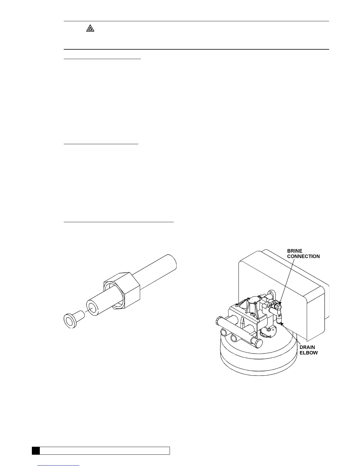
• Slip the white nut over one end of the tubing and press the plastic insert into the end of the tubing. Connect to the
brine valve and tighten nut. (Figure 6)
• Remove white nut and insert from wire tie around drain elbow.
• Slip the white nut over one end of the tubing and press the plastic insert into the end of the tubing. Connect to the
brine connection on the valve and tighten nut.
DRAIN LINE CONNECTION
Refer to Table 1, page 11 under the applicable tank size for drain line length and height limitations, and to Fig. 7.
• Remove 1/2” pipe clamp from end of drain elbow.
• Route a length of 1/2” drain line from the drain elbow to the drain.
• Fasten the drain line to the elbow with the clamp.
• Secure the drain line to the drain to prevent its movement during regeneration. A loop in the end of the tube will
keep it filled with water and will reduce splashing at the beginning of each regeneration.
NOTICE: Observe all plumbing codes. Most codes require an anti-siphon device or air gap at the discharge
point!
FILL THE SALT STORAGE CONTAINER
Fill the salt storage container with water until the level reaches about 1 inch above the salt support plate. Pour salt
into the container. Fill to within a few inches of the top.
FIG. 7
FIG. 6