12
CONDUIT CENTERLINE BENDING RADII
ASSEMBLY & OPERATING INSTRUCTIONS – 254 CONDUIT BENDER
(CONTINUED)
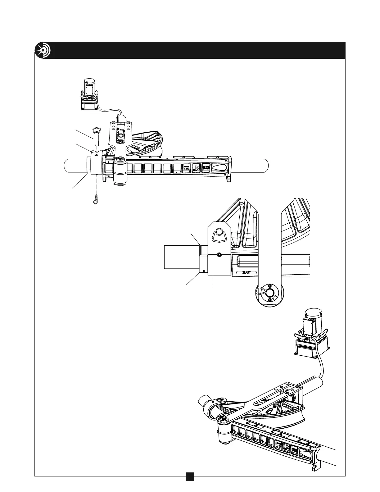
13. Place the correct size saddle around
the conduit as shown and rotate the
shoe as needed so that the saddle
hole and the shoe hole align. Insert
the saddle pin and secure with the
spring clip as shown in Figure 12.
NOTE: The saddle insert lip that
extends out should face away from
the follow bar (See figure 12A).
SADDLE
SADDLE INSERT LIP
SADDLE
BENDING MARK
P
14. Make sure the saddle is flush with the front
of the follow bar. The bending mark on the
conduit should be aligned with the front
edge of the saddle insert lip (see figure 12A).
Rotate the pump valve lever to the closed
position and activate the hydraulic pump
until the shoe contacts the conduit and the
saddle and follow bar are snug.
15. DO NOT BEGIN BEND. Before bending — To
determine the amount of cylinder travel for
the size, type and degree of bend, refer to
the cylinder travel and bender calibration
information on page 16.
16. Activate the hydraulic pump to begin the
bend. (See figure 12B).
NOTE: DO NOT over extend the hydraulic
cylinder during operation. This will allow
hydraulic fluid to escape the cylinder and
may cause a hazardous condition.
FIGURE 12A
FIGURE 12B
FIGURE 12