**DO NOT EXCEED RECOMMENDED VEHICLE TOWING WEIGHT!**
PAGE 2
80-96 FORD 1/2, 3/4, & 1 TON TRUCKS
97-98 FORD 3/4 & 1 TON TRUCKS
(WITH & WITHOUT OVERLOAD SPRINGS)
**OLD BODY STYLE** (LONG & SHORT BED)
60636
WARNING!! BRAKE, FUEL, AND ELECTRICAL LINES MAY NEED TO BE LOOSENED OR REPOSITIONED
TO PROVIDE CLEARANCE FOR NEW HARDWARE.
ALL MODELS REQUIRE MODIFICATION OR REMOVAL OF HEAT SHIELDS.
ON SHORT BED MODELS, CHECK FOR ADEQUATE TURNING CLEARANCE
BETWEEN THE FRONT OF ALL TRAILERS AND THE TRUCK CAB.
INSTALLATION STEPS CONTINUED
Curt Manufacturing Inc., warrants this product to be free of defects in material or workmanship at the time of retail purchase by the original purchaser. If the product is found to be defective,
Curt Manufacturing Inc., may repair or replace the product, at their option,when the product is returned, prepaid, with proof of purchase. Alteration to, misuse of, or improper installation of
this product voids the warrant. Curt Manufacturing Inc.'s liability is limited to repair or replacement of products found to be defective, and specificaly excludes liability for incidental or
consequential loss or damage.
4) Install the rear cross arm(has the deepest notches at the ends) by sliding it between the bed and the frame on the pass-
enger side in an inverted V position. In order to do this, the bed floor flange must be cut about 2" to the rear of the front most
bed frame rail (As shown in Figure 1) (NOTE: the notches must face the front of the truck) After it rests on the frames,
slide it towards the back of the truck. Rotate the arm so the notches are perpindicular to the truck bed. This process is made
easier by loosening the bed bolts in the frame rails behind the axle and using a crescent wrench or channels locks on the
slotted side of the cross arm to rotate it down on its long axis, placing the side without slots flush against the truck bed floor
and the cut-outs span the truck frame.
5) Install the front cross arm by sliding it between the bed and the frame on the passenger side in an inverted V position.
(NOTE: the notches must face the rear of the truck.) After it rests on the frame, slide it towards the front of the truck.
Rotate the arm so the notches are perpindicular to the truck bed and the cut-outs span the truck frame.
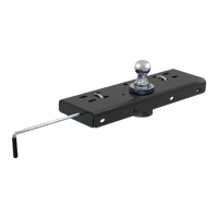
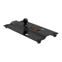
6) Before raising the center section in position between the cross arms with the ball cylinder towards the back of truck.
drop the back exhaust hanger. The round hitch receiver that protrudes from the top of the center section must fit through the
hole in the truck bed. Using (8) 1/2" carriage bolts, attach the center section to the holes in both cross arms. Finger tight
only with (8) 1/2" flange nuts. When re-attaching exhaust hanger, bend upward to adjust if tailpipes touch the center section.
7) Square the center section and cross arms across the frame. Place a 1 1/2" bolt with a washer through the back flange of
the sideplate into the rear cross arm and Finger tight only with a 1/2" flange nut. (As shown in Figure 2) Place a 1 1/2"
bolt with a flat washer through the front flange of the sideplate into the front cross arm. (As shown in Figure 2) Finger
tight only with a 1/2" flange nut. (REPEAT FOR OTHER SIDE) (NOTE: locate and release the brake line and fuel
line retaining clip from the frame rail on the driver side before attaching driver sideplate.) If bed bolts were loosend
in step 4, re-tighten them now.
8) Trucks without overload springs:
Align the large 1" hole and the rear hole on each sideplate to the existing holes in the
truck frame. Place a 1" bolt with a 1" washer through the inside of the frame. Place the tube spacer between the frame and
sideplate and attach a 1" washer, 1" lock washer, and 1" nut on the outside of the sideplates and Finger tight only. (As
shown in Figure 2) On the rear of the sideplate, place a 1/2" x 1 1/2" bolt through the inside of the truck frame through the
sideplate and attach with a 1/2" flange nut. (As shown in Figure 2) Finger tight only.
Trucks with overload springs:
The sideplates can be modified to fit trucks with overload springs. To do this, cut 10" off
the back of the sideplates(the narrow end of the sideplates). Install the 1" bolts as described in the above paragraph. Now
drill a 1/2" hole through the frame rails at the slot nearest the front of the sideplate. Attach with a 1/2" x 1 1/2" bolt and
washer from the inside of the frame and Finger tight only with a 1/2" flange nut.
9) With the sideplates installed on both sides, torque all 1" fasteners to 300 ft-lbs. and all 1/2" fasteners to 110 ft-lbs in the
following order:
First: Torque the center section to the front and rear cross arms.
Second: Torque the sideplate flanges to the front and rear cross arms.
Third: Torque the sideplates to the truck frame on both sides.
10) When installing the C-600 handle, it may be necessary to notch the bed floor flange on the driver side of the truck similarly to
the notch placed on the passenger side in step 4. The placement of the notch will be determined by the handle placement.
(REFER TO GOOSENECK HITCH INSTRUCTIONS FOR INSTALLATION AND OPERATING PROCEDURES)
Maintenance
(Required every 30 days or prior to use)
1. Keep hitch ball lubricated regularly. Use silicone spray or equivalent to prevent wear and rust.
2. Keep hitch assembly free of dirt and other foreign debris.
3. Check for proper torque on all nuts and bolts before each use. Also check for excessive wear.
4. Check for ball wear before each use. (Note: Do not tow trailer with worn or damaged parts.)
 Loading...