G
Page G-1
Repair and Service Manual
Read all of Section B and this section before attempting any procedure. Pay particular attention to all Notes, Cautions and Warnings
GENERAL
Do not hold vehicle on hill by using
accelerator and motor. Leaving the
motor in a stalled condition for more than 3-4 seconds will raise
the commutator bars resulting in unacceptable noise and accel-
erated brush wear and cause permanent damage to motor.
Disassembly of the motor is not recommended except to
replace a worn or noisy bearing. If the motor is disassem-
bled, it should be cleaned of any dirt buildup and the
brush length checked. Replace brushes if required.
Neither the motor housing nor field coil is available as
service items, therefore in the unlikely event of a failure
in either of these components, the entire motor must be
replaced.
Motor Removal
Disconnect the negative
(BL-) battery cable with
an insulated wrench
before attempting to remove wires from the motor
(see safety procedures in SAFETY section of this
manual). The shorting of motor wires could cause an
explosion.
Tool List Qty. Required
Insulated wrench, 9/16"............................................... 1
Chalk or paint pen....................................................... 1
Socket, 7/16", 3/8" drive.............................................. 1
Ratchet, 3/8" drive....................................................... 1
Using an insulated wrench, disconnect the negative (-)
battery cable from the battery (Ref Fig. 1 on page G-1).
Remove all wires from motor.
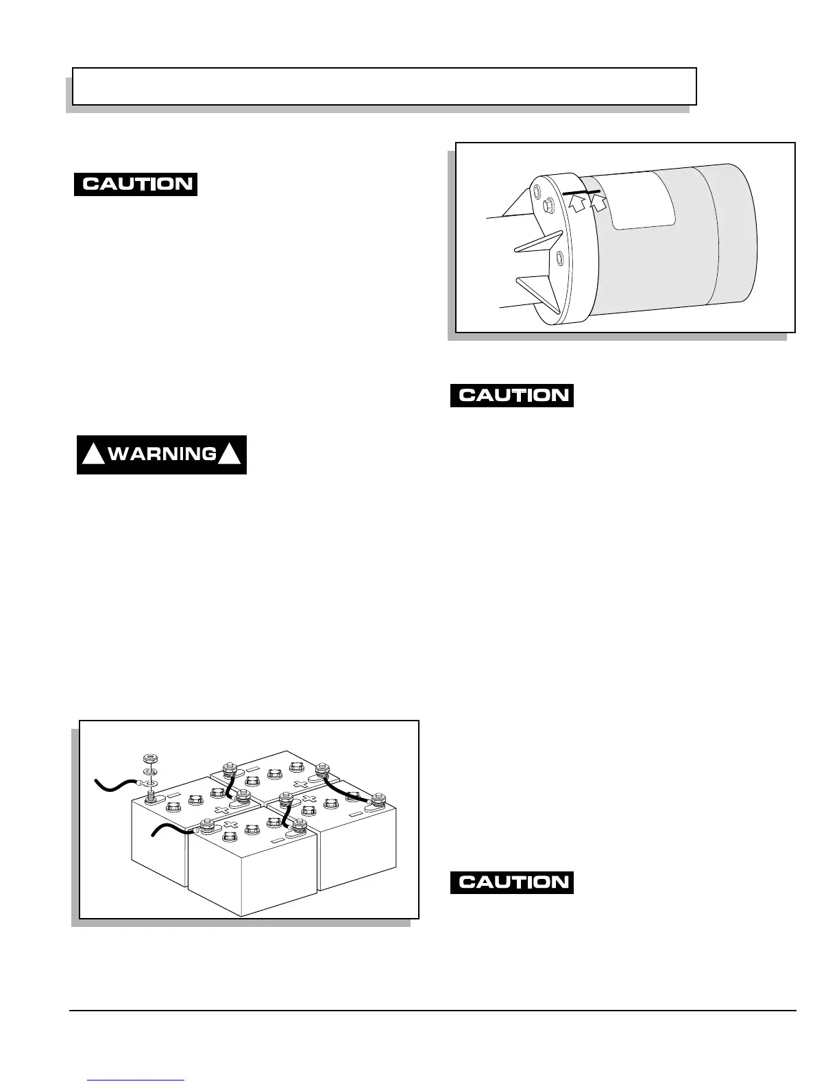
Mark both the axle and motor housings to permit realign-
ment during reassembly of motor to rear axle (Ref Fig. 2
on page G-1).
Take care not to damage the splines
when removing and reassembling the
motor to the rear axle housing.
Remove the three bolts that secure the motor to the axle
housing and carefully slide the motor straight out from
the axle splines.
Motor Disassembly
Tool List Qty. Required
Straight blade screwdriver........................................... 1
Ratchet, 3/8" drive....................................................... 1
Socket, 3/8", 3/8" drive................................................ 1
Plastic faced hammer.................................................. 1
Remove bearing cap (1) (Ref Fig. 3 on page G-2).
Remove bolts (2) that hold the commutator end cover (3)
to the motor housing (4).
Pull on commutator end cover to remove armature (5)
and cover (as an assembly) from the housing. A light tap
on the end cover may be necessary to loosen.
Bearing Replacement
Tool List Qty. Required
Heat gun or lamp.........................................................1
Arbor press.................................................................. 1
Bearing driver set ........................................................ 1
Snap ring pliers ........................................................... 1
Do not use a torch to heat the commu-
tator end cover. Only a moderate
amount of heat should be applied. Excessive heat will damage
the end cover and bearing.
Proper support must be given to the commutator end cover dur-
ing press operations. Inadequate and/or uneven support will
cause the end cover to fracture.
Fig. 1 Disconnect Battery Cable
! !
Remove BL-
Fig. 2 Mark Axle and Motor
MOTOR
 Loading...