MOTOR
Page G-2
Repair and Service Manual
Read all of Section B and this section before attempting any procedure. Pay particular attention to all Notes, Cautions and Warnings
To aid disassembly, heat only the commutator end cover
before attempting removal of the armature.
Once heated, place the commutator end cover/armature
assembly in press, giving as much support to the end
cover as possible, and press the armature out of the
bearing.
Push back each brush until its spring (15) is resting
against the side of the brush. This keeps the brushes out
of the way during bearing replacement (Ref Fig. 5 on
page G-3).
Remove internal snap ring (6) and heat the commutator
end cover again. Press bearing (7) out from commutator
end cover (3).
When installing bearing into end cover,
apply pressure against the bearing’s
outer race to avoid bearing damage.
Press the new bearing into the commutator end cover
using heat again to aid installation.
Install the snap ring.
If brushes are to be replaced, proceed now to
‘Brush Replacement’ before installing the
armature.
For proper location, the armature has a positive stop feature.
When installing armature into the bear-
ing/end cover assembly, support the
bearing’s inner race to avoid damage.
Press the armature into the new bearing using moderate
heat to aid installation.
Release brushes against commutator. Ensure the
springs are seated against the rear of the brushes and
are able to move freely.
Brush Replacement
Tool List Qty. Required
Wrench, 1/2"................................................................1
Ratchet, 1/4" drive .......................................................1
Socket, 5/16", 1/4" drive ..............................................1
Brushes should be measured as shown and replaced
when the minimum dimension of .62" (16 mm) is reached
(Ref Fig. 4 on page G-3).
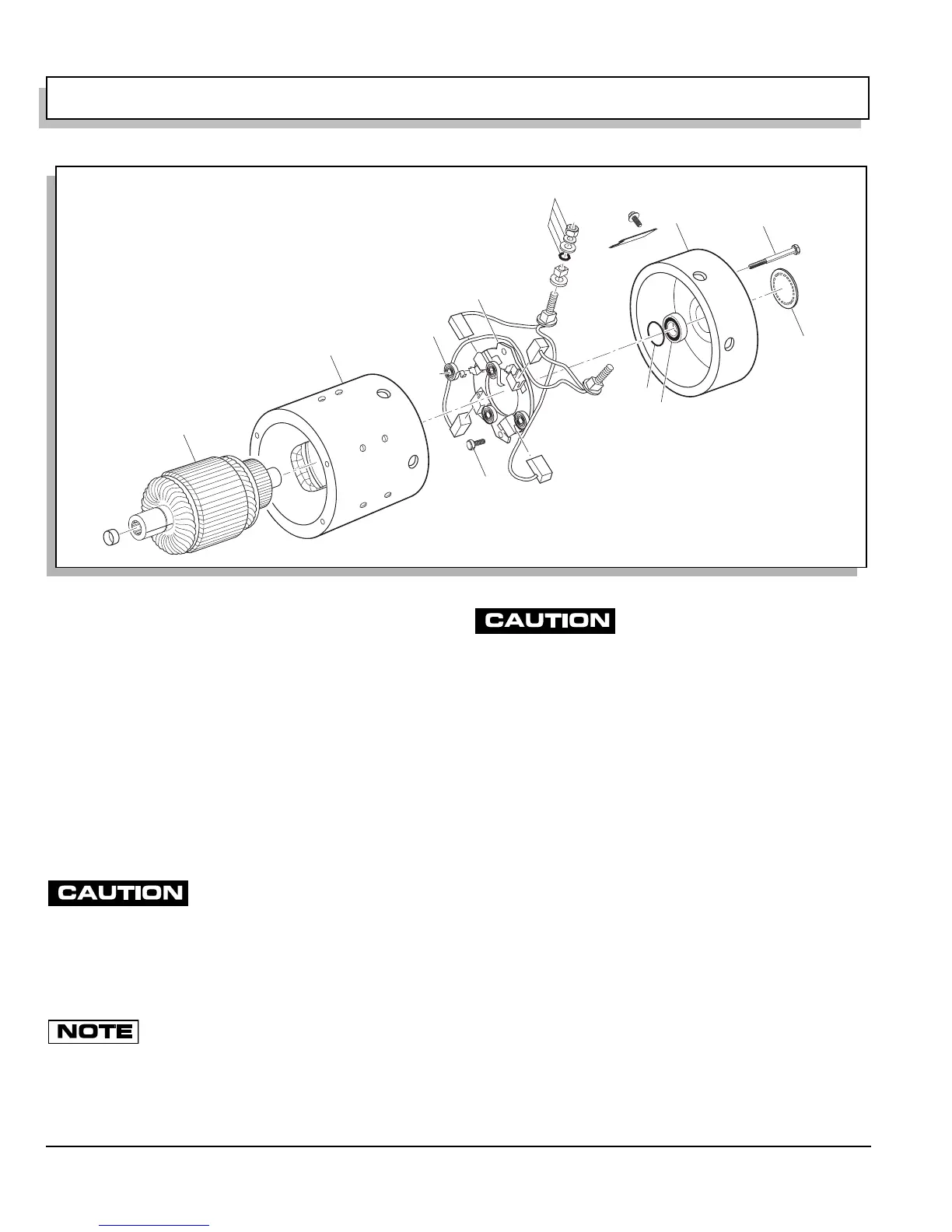
Remove brush terminal hardware (12) at A1 and A2 (Ref
Fig. 3 on page G-2).
Remove screws (13) securing brush plate (14). Remove
brushes, rigging and brush plate.
Pull back each brush until each of the springs (15) rest
against the side of its brush (Ref Fig. 5 on page G-3).
Remove brushes and replace with new brush replace-
ment kit. Locate springs against the side of each brush.
Fig. 3 Motor Components
A1
A2
1
2
3
4
5
6
7
12
13
14
15