Page L-7
Repair and Service Manual
B
B
BATTERIES AND CHARGING
Read all of Section B and this section before attempting any procedure. Pay particular attention to Notices, Cautions, Warnings and Dangers.
problem with the low reading cell(s).
As a battery ages the specific gravity of the electrolyte
will decrease at full charge. This is not a reason to
replace the battery, providing all cells are within fifty
points of each other.
Since the hydrometer test is in response to a vehicle
exhibiting a performance problem, the vehicle should be
recharged and the test repeated. If the results indicate a
weak cell, the battery or batteries should be removed
and replaced with a good battery of the same brand,
type and approximate age.
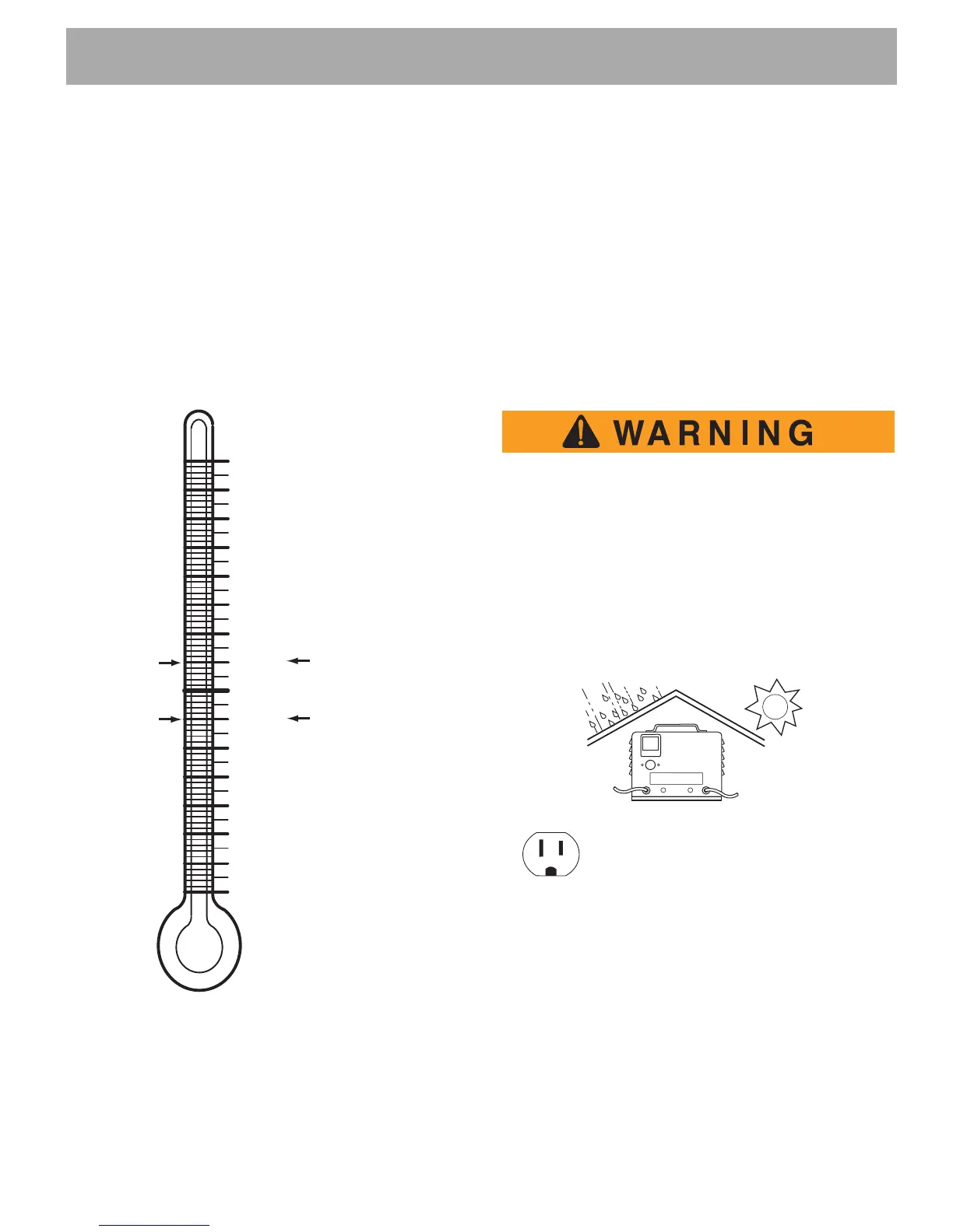
Fig. 8 Hydrometer Temperature Correction
BATTERY CHARGER
Description
The battery charger accompanying this vehicle is 120
volt AC, 60 Hz input with 48 volt DC output. Contact
charger manufacturer for maintenance or service parts.
For service assistance, contact Service Parts Depart-
ment, 1-800-227-7029.
Portable Charger Installation
Portable chargers must be mounted on a plat-
form above the ground or in such a manner as
to permit the maximum air flow underneath and
around the charger. Do not block or obstruct
the airways as overheating may result which
could cause serious damage to the charger
and create the potential for fire.
If the charger is operated in an outdoor location, rain
and sun protection must be provided.
Fig. 9 Charger Installation
A dedicated circuit is required for the charger. Refer to
the charger manual for appropriate circuit protection.
The charger may remain plugged into the AC outlet. To
charge the vehicle, refer to the instruction labels on the
charger. Insert the DC plug completely into the vehicle
receptacle located on the panel underneath the driver
seat (Ref. Fig. 10). After inserting the polarized DC plug,
160 71 +.032
+.030
150 66 +.028
+.026
140 60 +.024
+.022
130 54 +.020
+.018
120 49 +.016
+.014
110 43 +.012
+.010
100 38 +.008
+.006
90 32 +.004
+.002
80 27 0
–.002
70 21 –.004
–.006
60 16 –.008
–.010
50 10 –.012
–.014
40 4 –.016
–.018
30 –1 –.020
–.022
2 –7 –.024
–.026
10 –12 –.028
EXAMPLE #1:
Electrolyte Temperature
Above 80° F (27° C)
Electrolyte temperature
90° F (32° C)
Hydrometer reading 1.250
1.250 + .004 = 1.254
corrected specific gravity
Electrolyte Temperature
Below 80° F (27° C)
Electrolyte temperature
70° F (21° C)
Hydrometer reading 1.250
1.250 - .004 = 1.246
corrected specific gravity
EXAMPLE #2:
° F ° C
Electrolyte
Temperature
Provide Protection From Elements
Do Not Block Louvered Airways
NEMA 15 - 5R Grounded AC Receptacle
110 - 120 VAC. Dedicated 15 AMP Circuit
Locations outside the US and Canada: Reference
appropriate local electrical code and charger manu-
facturer recommendations for AC power requirements