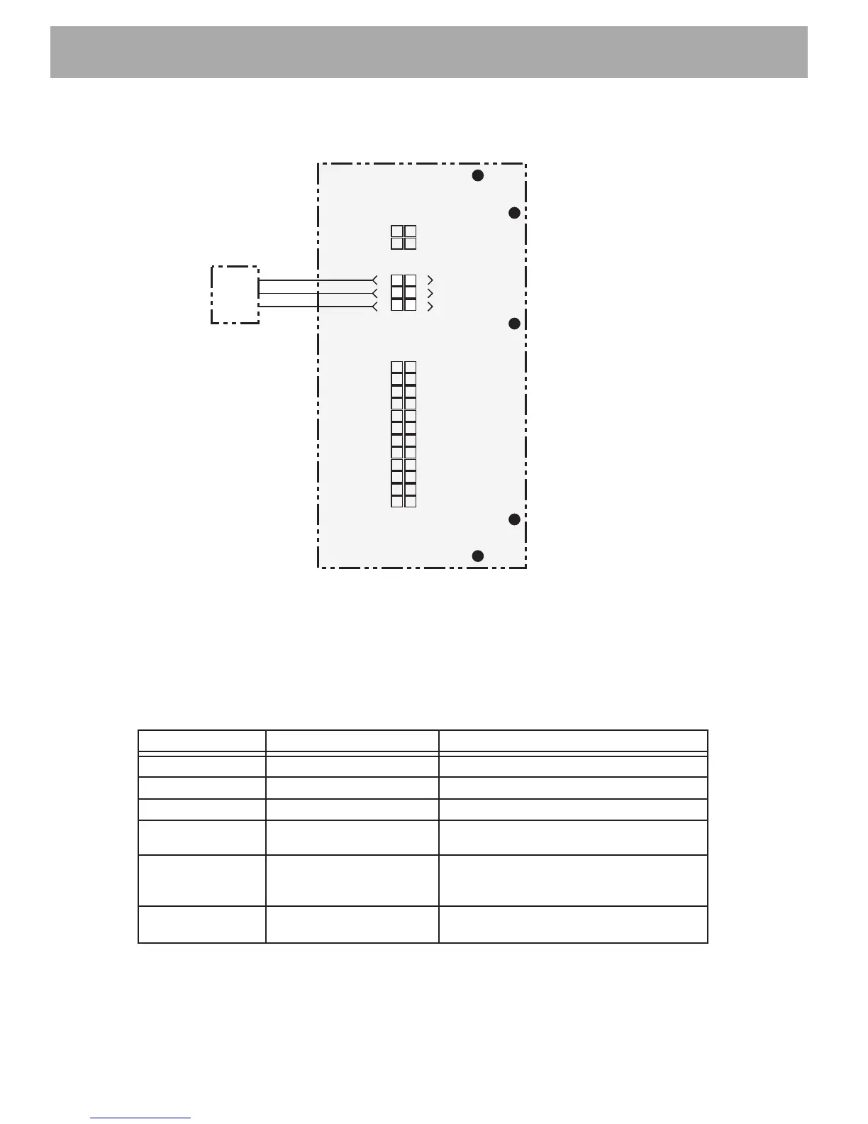
Fig. 13 J-2 Pin Connector Diagnostics
1
2
3
4
5
6
7
8
9
10
11
12
13
14
15
16
17
18
19
20
21
22
23
24
J1
SPARE
SPARE
SPARE
F2
B+
M-
B-
F
1
J3
J2
Speed
Sensor
4
5
6
1
2
3
All tests are to be performed with the negative lead of the D
VOM connected to the negative side
of battery pack voltage.
The positive lead of the DVOM is used to probe the controller connections. Leave connections
plugged in the controller
Armature will need to be rotated for this test. Jack vehicle up on the passenger side and rotate
the rear wheel by hand
Pin number Voltage
If not/ Then
J2-1 Spare
J2-2 Spare
J2-4 0 volts Verify sensor harness and connection.
This connection serves as the sensor ground
J2-6 16 - 17 volts Verify sensor harness. Possible faulty
controller
J2-3 Spare
J2-5 0 - 6.5 volts Verify the speed sensor and harness . This
connection provides the flash voltage from
the sensor while the armature rotates.
Ground
Input
+15V