Custers Hydraulica B.V. Venray NL
26-mrt-20 www.custers.nl
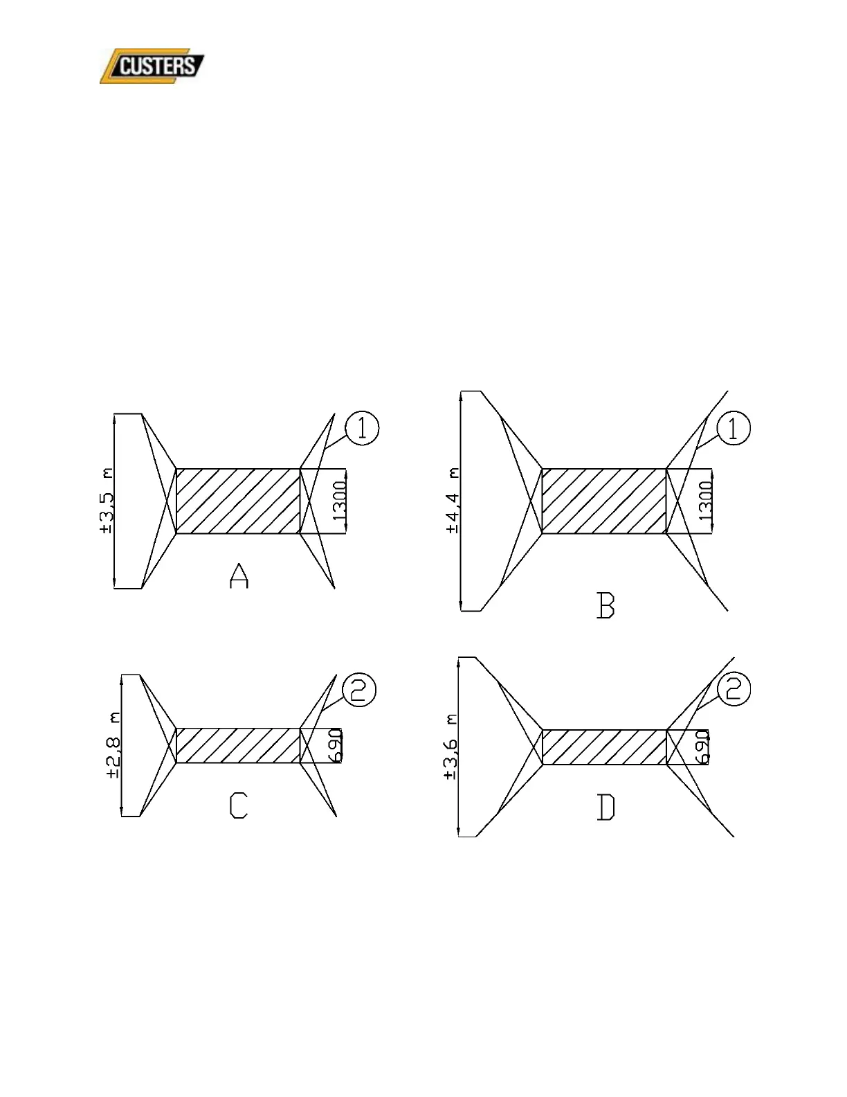
5.4 Outriggers and expansion arches
The outriggers/expansion arches specified in the table must always be fitted once the lower
edge of the scaffold has been erected. During assembly, the upper sides of the
outriggers/expansion arches must be connected to the underside of the rungs in order to
prevent them from sliding upwards unintentionally.
The basic form to be used, i.e. the arch to be used (small or large), can be read in the
composition tables.
The basic forms shown below must be strictly adhered to!
If the designated form is different, ballast weights may be required; please contact the
manufacturer/supplier for this. Small arches may be replaced by small legs and large arches
by large legs, provided that the use of legs follows the same basic form as the arches. This
means that the outriggers when viewed from the top, must be mounted in the same position
as the expansion arches.
Fig.2
Basic forms
A: Small arch, length 1300 mm B: large arch, length 2000 mm
C: Small arch, length 1300 mm D: large arch, length 2000 mm
1: Brace, length 2500 mm, art. nr. 9501.200.030CR
2: Brace, length 1913 mm, art. nr. 9501.200.048CR