Power values are grossly No voltage input to trip unit. Check PT disconnect plug is installed.
in error. (1050 Trip Units
only) Frequency incorrect Verify operating frequency with OPTIMizer. I.B. 29C892, Para. 3-6
Trip unit may be the problem. Replace trip unit Para. 5-3
“Connection Failure” when FIRST DISCONNECT VOLTAGE SUPPLY TO TERMINALS C9 AND C10 ON RD AND SPB
OPTIMizer is plugged in. BREAKERS OR 5 AND 6 ON DSII BREAKERS TEMPORARILY. (Place drawout breakers
in disconnect position which will remove voltage supply)
OPTIMizer not working or cord not Verify OPTIMizer operation on another breaker. I.B. 29C892
properly plugged into OPTIMizer. Para. 2-2.2 & 3-2
Cord not properly plugged into Check connection. If unit status LED is blinking, Para. 2-5.1
breaker. connection is OK.
Rating plug is not installed or is Instantaneous LED will be on. Install rating plug Para. 2-6 & 5-4.2
loose. and/or check for loose connections.
Rating plug is open internally Instantaneous LED will be on. Replace rating Para. 5-4.2, Table 2.1
plug.
Trip unit may be the problem. Replace trip unit Para. 5-3
RECONNECT VOLTAGE SUPPLY
BIM will not communicate Breaker address is > 32 (HEX) Check address with OPTIMizer and change as I.B. 29C892
with trip unit. required. Para. 3-5.1
No auxiliary power If possible, open breaker or reduce breaker Symptom: “Unit
current <20% of frame rating. Then check that Status LED is not
unit status LED is blinking. If not, see first blinking.”
symptom in this portion of the table.
Rating plug is not installed Instantaneous LED will be on. Install rating Para. 2-6 & 5-4.2
plug and/or check for loose connections.
Rating plug is open internally Instantaneous LED will be on. Replace rating Para. 5-4.2, Table 2.1
plug.
Open INCOM connection Check connections at terminals C11 and C12 on Table A.1
RD and SPB breakers or C6 and C7 on DSII Wiring Diagrams
breakers. The transmit LED should flash when
there is communication. With the external con-
nections to C11 and C12 or C6 and C7 opened
temporarily, the resistance across C11 and C12
or C6 and C7 should be approximately 2.5 ohms.
Trip unit may be the problem. Replace trip unit Para. 5-3
I.B. 29C891B
Page 49
Effective 11/98
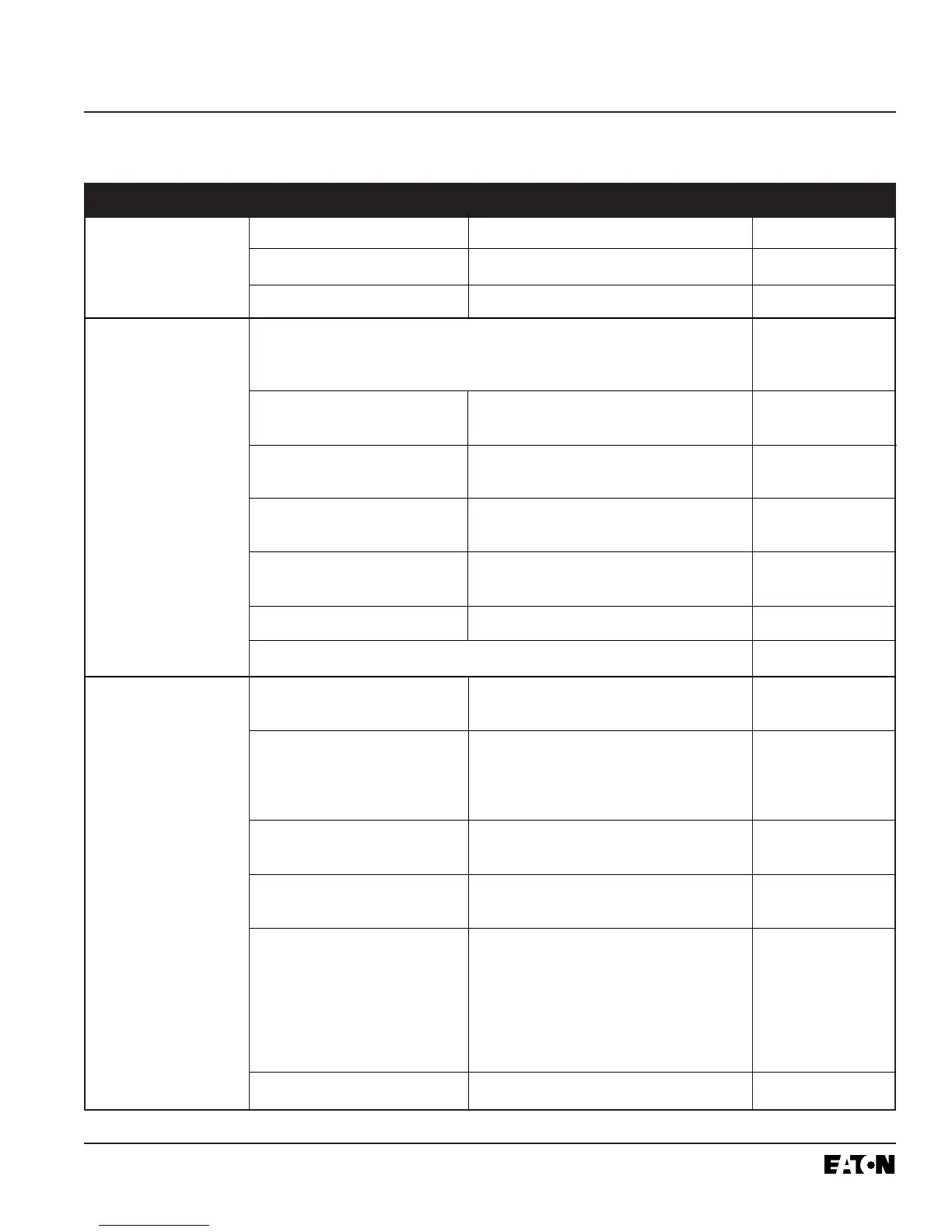
Table 5.1 Troubleshooting Guide (continued from previous page)
Symptom Probable Cause Possible Solution(s) References
 Loading...