breakers. The transmit LED should flash when
there is communication. With the external con-
nections to C11 and C12 or C6 and C7 opened
temporarily, the resistance “looking into” C11
and C12 or C6 and C7 should be approximately
2.5 ohms.
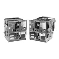
R-Frame, SPB Pow-R and DSII/DSLII Circuit Breakers without Auxiliary Power
Unit Status LED is not Current thru breaker is < 20% of No problem. Status LED will not operate with N.A.
blinking. frame rating. breaker currents < 20% of frame rating.
Trip unit may be the problem. Replace trip unit Para. 5-3
As soon as current starts Rating plug is not installed or is Install rating plug and/or check for loose con- Para. 2-6 & 5-4.2
to flow thru the breaker, loose. Breaker cannot be closed nections.
it trips and the instantan- without rating plug installed.
eous trip LED comes on.
Rating plug is open internally Replace rating plug Para. 5-4.2, Table 2.1
Trip unit may be the problem. Replace trip unit Para. 5-3
LED does not come on Battery installed backwards Install correctly Para. 5-4.1
when battery check
button is pressed. Dead battery Replace battery Para. 5-4.1, Table 2.2
Bad rating plug Replace rating plug Para. 5-4.2, Table 2.1
“Connection Failure” when OPTIMizer not working or cord not Verify OPTIMIzer operation on another breaker. I.B. 29C892
OPTIMizer is plugged in. properly plugged into OPTIMizer. Para. 2-2.2 & 3-2
Cord not properly plugged into Check connection. If unit status LED is blinking, Para. 2-5.1
breaker. connection is OK.
Rating plug is not installed or is Instantaneous LED will be on. Install rating plug Para. 2-6 & 5-4.2
loose. and/or check for loose connections.
Rating plug is open internally. Replace rating plug Para. 5-4.2, Table 2.1
Trip unit may be the problem. Replace trip unit Para. 5-3
Breaker trips on ground There actually is a ground fault. Find location of the fault N.A.
fault.
On four wire systems the neutral Check connections at terminals D6 and D7 on Table A.1
current sensor may not have the RD and SPB breakers or 19 and 20 on DSII Wiring Diagrams
correct ratio or be properly con- breakers. Check that the neutral current sensor
nected. ratio matches the breaker. Check that the con-
nections from the neutral current sensor to the
(Continues on next page) breaker are not reversed. Check that the shorting
I.B. 29C891B
Page 51
Effective 11/98
Table 5.1 Troubleshooting Guide (continued from previous page)
Symptom Probable Cause Possible Solution(s) References