4
The output impedance of this signal is 100 ohms and can source 10 milliamps of
current. The analog-interface cable can also be used to supply power to the GFM.
The power requirement is (12 - 28) vdc @ 100 ma. This cable also has the
connections for the Fault Relay and Modbus® RS-485 serial port.
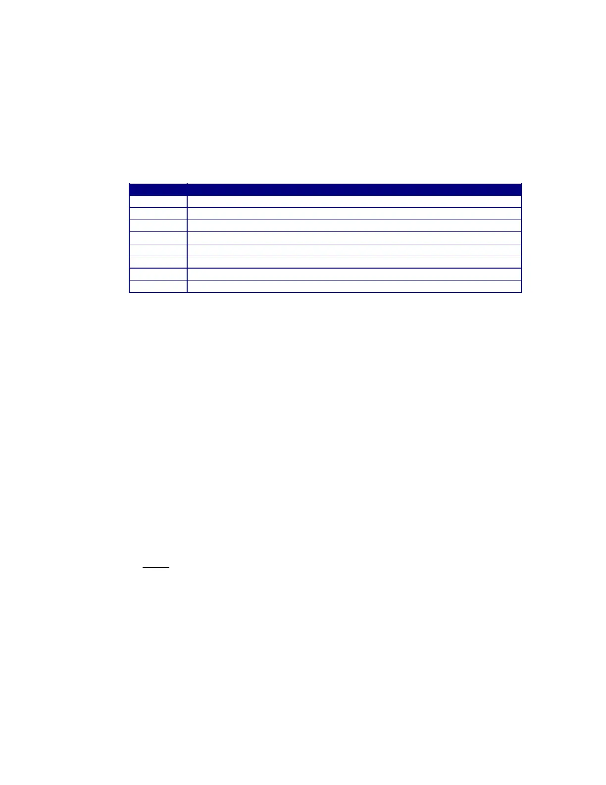
The following is the pin out for the GFM AUX Cable (P/N: A3W0352).
Modbus RS-485 D+ serial port
User supplied Power Input VIN+ (12-28 VDC @100 ma)
CR-A - Will be active when gas flow is within programmed limits.
CR-B – Will be active when gas flow is within programmed limits.
User supply power common VCOM
Modbus RS485 and Vout analog common
Modbus RS-485 D- serial port
Gas Flow Analog output VOUT+ (0.00 – 2.55 vdc)
2.4 Gas Flow Limits
The GFM can be used to test for High/Low gas flow limits. An internal fault relay
will be set (CLOSED) when the gas flow is within the programmed limits. The fault
relay can be interfaced to an external weld fixture controller.
2.5 Gas Flow Volume
The GFM can also be used to monitor accumulated gas flow and to provide an
indication when the volume in a gas cylinder has reached a programmed minimum
limit. The GFM will calculate the volume of gas used based on the measure flow
rate. If the user programs the minimum volume for safe operation, the GFM will
indicate when the estimate minimum volume has been reached. The GFM will set
a fault relay when the estimated volume has decreased below the programmed
minimum. Setting the starting volume “V” to 0 disables the function.
NOTE: THE LOW GAS VOLUME FAULT WILL NOT ACTIVATE THE FAULT RELAY BUT
WILL INDICATE THE FAULT CONDITION BY SETTING A MODBUS® COIL
CR15.
 Loading...