31
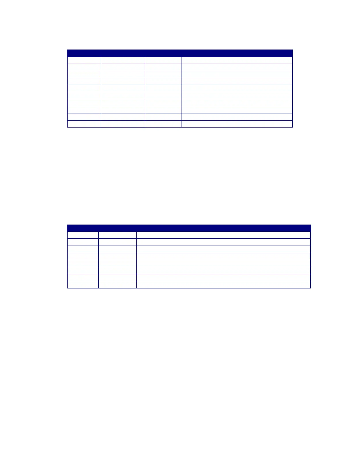
12.3 MODBUS REGISTER REG [1..10]
Low Volume Alarm (Not Enabled)
Accumulated Gas Flow since last reset
Total Gas Flow hours since last reset
Total Minutes (MSB) and Seconds(LSB)
Peak Gas flow rate for last Flow period
Peak Flow rate Time for last flow period
12.4 MODBUS SERIAL PORT CONNECTIONS
To use the Modbus communications port the user must connect a suitable RS-485 driver and Modbus
host device to the GFM Auxiliary cable A3W0352. Connect the RS-485 driver output “A/( TxD-/RxD-)”
to the “BLUE” (Pin 7) wire. Connect the RS-485 driver output “B/( TxD+/RxD+) ” to the WHITE (Pin 1)
wire. Connect the RS-485 driver output “COM” to the “PINK” (Pin 6) wire. The RS-485 driver “COM”
should also be connected to the user supplied GFM Power Input common.
The following is the pin out for the GFM AUX Cable (P/N: A3W0352).
Modbus RS-485 B(TxD+/RxD+) serial port
User supplied Power Input VIN+ (12-28 VDC @100 ma)
CR-A - Will be active when gas flow is within programmed limits.
CR-B – Will be active when gas flow is within programmed limits.
User supply power common VCOM
Modbus RS485 and Vout analog common
Modbus RS-485 A(TxD-/RxD-) serial port
Gas Flow Analog output VOUT+ (0.00 – 2.55 vdc)